Optocoupler isolation circuit based on GH063L

An optocoupler isolation circuit, optocoupler technology, which is applied in the direction of logic circuits using optoelectronic equipment, logic circuits using specific components, etc., can solve problems such as signal distortion and affect signal acquisition accuracy, and achieve good isolation and anti-interference ability. , the effect of good isolation and anti-interference ability, good electrical isolation and anti-interference ability

Pending Publication Date: 2021-04-02
WUHAN AVIATION INSTR
View PDF0 Cites 0 Cited by
  • Summary
  • Abstract
  • Description
  • Claims
  • Application Information

AI Technical Summary

Problems solved by technology

However, when the current isolation circuit isolates high-frequency signals such as 40,000 Hz, the signal will be distorted, which will affect the acquisition accuracy of the signal.

Method used


Image

  • Optocoupler isolation circuit based on GH063L
  • Optocoupler isolation circuit based on GH063L
  • Optocoupler isolation circuit based on GH063L

Examples


Embodiment 1

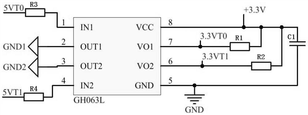
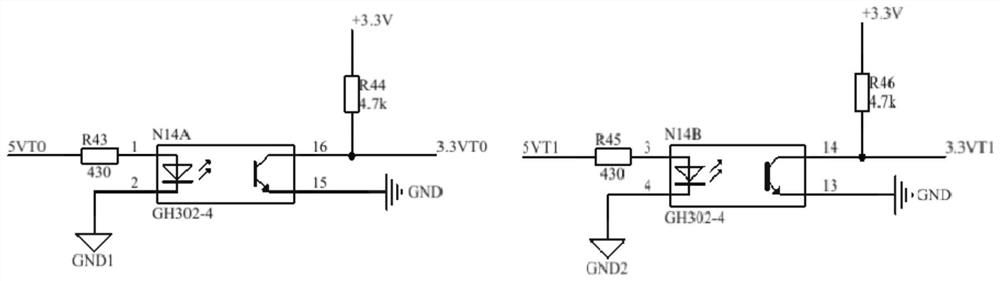
[0021] Example 1. An optocoupler isolation circuit based on GH063L, constituted as figure 1 and 2 As shown, including the GH063L optocoupler, the two output pins VO1 and VO2 of the GH063L optocoupler are respectively connected to one end of the pull-up resistor R1 and the pull-up resistor R2, and the other ends of the pull-up resistor R1 and R2 are connected to the GH063L optocoupler The VCC pin is connected, and the VCC pin is externally connected to a 3.3V voltage; the IN1 and IN2 pins of the GH063L optocoupler are signal input terminals, and the VO1 and VO2 pins are signal output terminals.

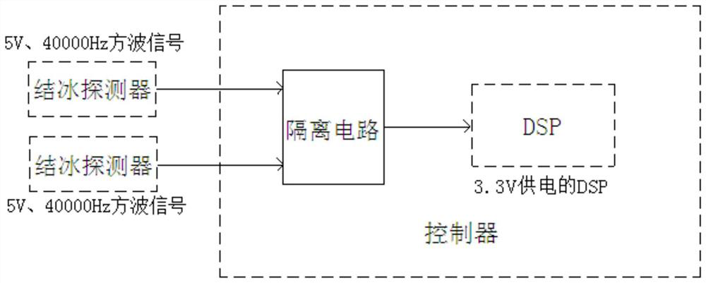
[0022] The icing detectors located on both sides of the machine head input two input signals to the GH063L optocoupler through IN1 and IN2 pins. The input signals drive the light-emitting diodes in the GH063L optocoupler to emit light, and the emitted light is detected by the photodetector in the GH063L optocoupler. Receive and generate photocurrent, and the photocurrent is further ...


PUM


Abstract

The invention discloses an optical coupling isolation circuit based on GH063L. The circuit comprises a GH063L optocoupler, two output pins VO1 and VO2 of the GH063L optocoupler are connected with oneend of a pull-up resistor R1 and one end of a pull-up resistor R2 respectively, the other end of the pull-up resistor R1 and the other end of the pull-up resistor R2 are connected with a VCC pin of the GH063L optocoupler, and the VCC pin is externally connected with 3.3 V voltage; and pins IN1 and IN2 of the GH063L optocoupler are signal input ends, and pins VO1 and VO2 of the GH063L optocoupler are signal output ends. The circuit has the advantages of being simple in structure, capable of preventing high-frequency signal distortion and high in high-frequency signal isolation capacity and anti-interference capacity.

Description

technical field [0001] The invention belongs to the technical field of isolation circuits, and relates to an optocoupler isolation circuit based on GH063L. Background technique [0002] In the field of aircraft icing detection, one icing detector is installed on each side of the nose of the aircraft. The icing detector outputs a square wave signal with an amplitude of 5V and a frequency of 40000Hz based on the principle of magnetostriction. The thickness of ice on the surface is different, and the frequency generally changes in the range of 39000Hz to 40000Hz, and the matching controller needs to collect the frequency signal. In the field of aviation, electromagnetic compatibility has always been a difficult problem for major airborne product suppliers. For the icing detection system, the problem of electromagnetic compatibility is a crucial point in the process of transmitting the frequency signal from the detector to the controller. Therefore, it is necessary to design a...

Claims


Application Information

Patent Timeline
Patent Type & Authority Applications(China)
IPC IPC(8): H03K19/14
CPCH03K19/14
Inventor 何涛涛李昂徐弘炜郭玉东张楚汉陈壹
Owner WUHAN AVIATION INSTR
Why Eureka
Try Eureka