Eureka AIR delivers breakthrough ideas for toughest innovation challenges, trusted by R&D personnel around the world.

Tail gas treatment system for chemical production

A technology for exhaust gas treatment and chemical production, which is applied in the direction of air quality improvement, the use of liquid separation agents, chemical instruments and methods, etc., can solve the problems of increasing treatment costs, single structure, and low utilization rate of spray liquid, and achieves improved utilization. efficiency, ease of use

Active Publication Date: 2021-04-06
HUAINAN UNITED UNIVERSITY
View PDF7 Cites 1 Cited by
  • Summary
  • Abstract
  • Description
  • Claims
  • Application Information

AI Technical Summary

Problems solved by technology

[0003] At present, the common exhaust gas treatment device removes the impurities soluble in water by spraying. However, the structure of this method is relatively simple, and the utilization rate of spray liquid is not high, resulting in waste of resources and increasing treatment costs.

Method used


Image

  • Tail gas treatment system for chemical production
  • Tail gas treatment system for chemical production
  • Tail gas treatment system for chemical production

Examples


Embodiment 1

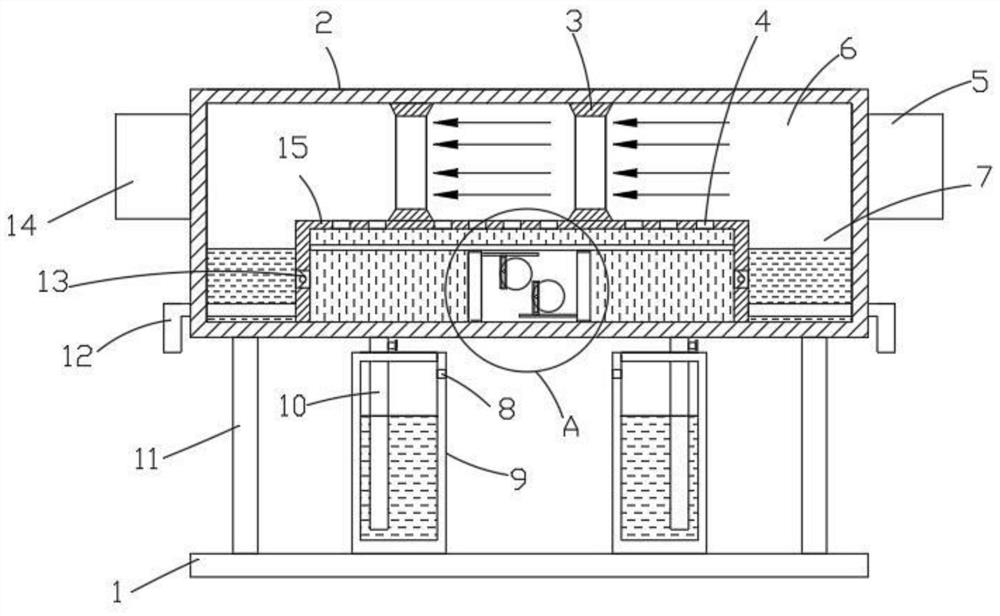
[0028] see Figure 1-4 , a chemical production tail gas treatment system, comprising a substrate 1, a processing box 2 fixed above the substrate 1, the opposite sides of the processing box 2 are respectively provided with an inlet pipe 5 and an outlet pipe 14.

[0029] The inner bottom of the treatment box 2 is provided with an inner shell 15 , and a treatment chamber 6 through which waste gas circulates is formed between the outer side of the inner shell 15 and the inner wall of the treatment box 2 . The bottom of the treatment chamber 6 has at least one liquid accumulation area 7 .

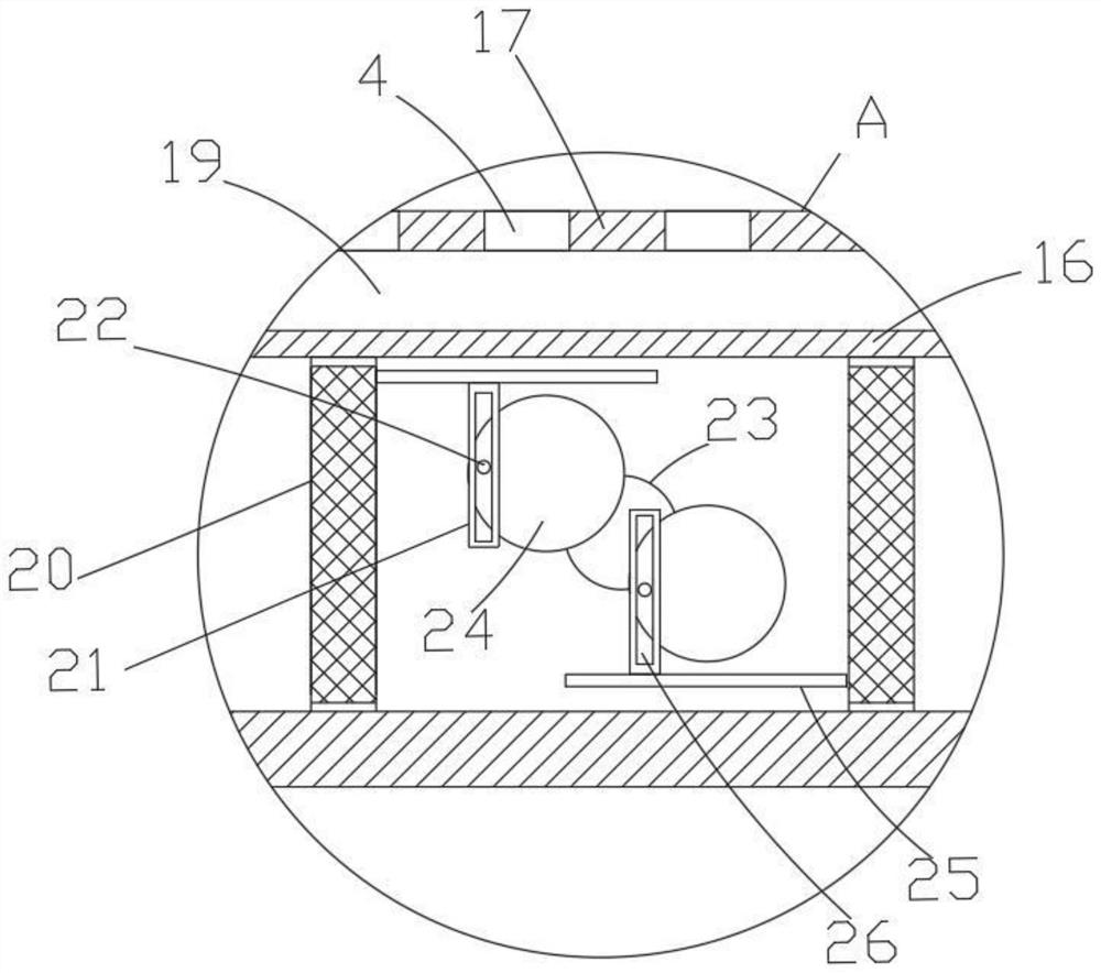
[0030] The inner partition 16 is fixed inside the inner casing 15, the liquid storage chamber 19 is formed between the inner partition 16 and the top shell of the inner casing 15, and the liquid replenishment chamber is formed between the inner partition 16 and the bottom casing of the inner casing 15, and the Two push plates 20 are arranged symmetrically in the liquid replenishing chamber, and ...


PUM


Abstract

The invention relates to the technical field of chemical tail gas treatment, and discloses a tail gas treatment system for chemical production. The tail gas treatment system comprises a base plate and a treatment box fixed on the base plate, a gas inlet pipe and a gas outlet pipe are arranged on the two opposite sides of the treatment box correspondingly, and an inner shell is arranged at the bottom in the treatment box. A treatment cavity for waste gas circulation is formed between the outer side of the inner shell and the inner wall of the treatment box, at least one liquid accumulation area is arranged at the bottom of the treatment cavity, an inner partition plate is fixed in the inner shell, a liquid storage cavity is formed between the inner partition plate and a top shell body of the inner shell, and a liquid supplementing cavity is formed between the inner partition plate and a bottom shell body of the inner shell. Two push plates are symmetrically arranged in the liquid supplementing cavity. The push plates are in sealed contact with the inner wall of the inner shell, a driving mechanism is arranged between the two push plates and used for driving the push plates to reciprocate, and waste gas treatment liquid is stored on the sides, away from each other, of the two push plates. The tail gas treatment system is simple in structure, chemical tail gas can be conveniently sprayed, treatment liquid can be recycled multiple times, the utilization rate is increased, and energy is saved.

Description

technical field [0001] The invention relates to the technical field of chemical tail gas treatment, in particular to a tail gas treatment system for chemical production. Background technique [0002] At present, chemical waste gas refers to the poisonous and harmful gas discharged from chemical plants in chemical production. Chemical waste gas often contains many types of pollutants, complex physical and chemical properties, and different toxicity, which seriously pollutes the environment and affects human health. The composition of chemical waste gas produced by different chemical production industries varies greatly. For example, the waste gas produced by the chlor-alkali industry mainly contains chlorine, hydrogen chloride, vinyl chloride, mercury, acetylene, etc., and the waste gas produced by the nitrogen fertilizer industry mainly contains nitrogen oxides, urea dust, carbon monoxide, ammonia, sulfur dioxide, methane, etc. [0003] At present, the common exhaust gas t...

Claims


Application Information

Patent Timeline
IPC IPC(8): B01D53/18B01D53/78B01D47/06
CPCB01D53/18B01D53/78B01D47/063Y02A50/20
Inventor 何晓文
Owner HUAINAN UNITED UNIVERSITY
Why Eureka
Eureka Blog
Learn More