
Plate positioning and drilling system and positioning method

A technology for plates and drill bits, applied in positioning devices, boring/drilling, cleaning methods and utensils, etc., can solve problems such as affecting the drilling efficiency, and achieve the effect of improving drilling efficiency

Active Publication Date: 2021-04-06
布莱凯特设备(苏州)有限公司
View PDF6 Cites 0 Cited by
  • Summary
  • Abstract
  • Description
  • Claims
  • Application Information

AI Technical Summary

Problems solved by technology

[0004] In order to solve the problem that the disassembly and assembly of the plate on the fixture affects the drilling efficiency, the application provides a plate positioning drilling system and positioning method

Method used


Image

  • Plate positioning and drilling system and positioning method
  • Plate positioning and drilling system and positioning method
  • Plate positioning and drilling system and positioning method

Examples


Embodiment Construction

[0043] The following is attached Figure 1-6 The application is described in further detail.

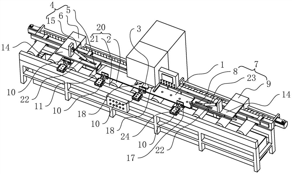
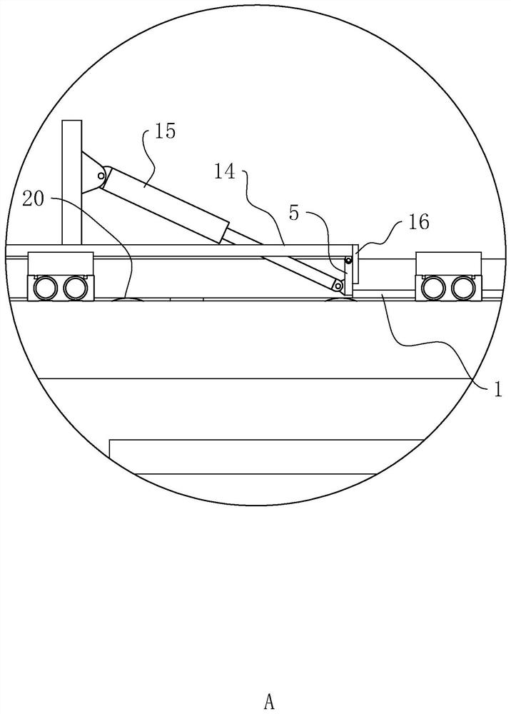
[0044] The embodiment of the present application discloses a plate positioning drilling system. refer to figure 1 The plate 1 positioning drilling system includes a drill bit 18, a linear transmission line 20 located directly below the drill bit 18, a second pusher plate 10, a second material blocking plate 11, and a pressure plate 3 located on both sides of the linear transmission line 20. , Pushing mechanism 4 and blocking mechanism 7, wherein drill bit 18 is positioned at the side of pressing plate 3, and drilling bit 18, holding plate 3, the second pushing plate 10 and the second blocking plate 11 are all positioned at pushing mechanism 4 and blocking Between the feeding mechanism 7.

[0045] refer to figure 1 , the clamping plate 3 is used to press the plate 1 on the linear transmission line 20 so that the drill bit 18 can drill holes; Push the plate 1 to move along the str...


PUM


Abstract

The invention relates to the field of machining equipment, in particular to a plate positioning and drilling system. The plate positioning and drilling system comprises conveying wheels for conveying a plate along a straight line, a pressing plate for compressing the plate on the conveying wheels, and a pushing mechanism, wherein the pushing mechanism comprises a first pushing plate with the height adjustable and a first moving mechanism; the first pushing plate can push one end of the plate, and the plate can pass below the first pushing plate; and the first moving mechanism is used for driving the first pushing plate to move in the direction perpendicular to the axial direction of the conveying wheels. According to the plate positioning and drilling system, the plate neither needs to be clamped on a clamp during each drilling nor needs to be detached from the clamp when the drilling is finished, so that the drilling efficiency of large batches of plates is greatly improved compared with the mode that the plates are clamped by the clamp for drilling; and the automatic machining of the whole process from transferring of the plate to the position below a drill bit to transferring away after drilling is completed is realized.

Description

technical field [0001] The present application relates to the field of mechanical processing equipment, in particular to a plate positioning drilling system and positioning method. Background technique [0002] In the field of mechanical processing, the operation of drilling a plate is often involved, and this operation is mainly performed on a drilling machine. For workpieces that require high precision in the position of the drilled holes, the plate workpiece not only needs to be reliably fixed, but also needs to be precisely positioned for the position of the hole. [0003] When drilling a plate on a drilling machine, it is necessary to fix the plate at a specified position with a jig first, then start the drilling machine to start drilling, after finishing all the hole positions, remove the plate from the fixture, and then clamp another plate Continue drilling on the jig. Because a large amount of man-hours are wasted in removing and installing the plates on the fixtur...

Claims


Application Information

Patent Timeline
Patent Type & Authority Applications(China)
IPC IPC(8): B23B41/00B23B47/22B23Q3/06B23Q11/00B23Q11/08B08B5/02
CPCB23B41/00B23Q5/22B23Q3/06B23Q11/005B23Q11/08B08B5/02
Inventor 杨宗玉
Owner 布莱凯特设备(苏州)有限公司
Learn More