Multi-wire sawing machine wire bow height automatic adjustment control system and method

A multi-wire cutting machine and automatic adjustment technology, applied in the control of workpiece feed movement, manufacturing tools, grinding drive devices, etc., can solve the problems of increasing sample trial production costs, inapplicable cutting environment, and rising production costs, etc., to achieve The effect of reducing trial production costs, labor costs, and consumable costs

Pending Publication Date: 2021-04-06
PHASE MOTION CONTROL SOLUTION WUHAN CO LTD
View PDF0 Cites 1 Cited by
  • Summary
  • Abstract
  • Description
  • Claims
  • Application Information

AI Technical Summary

Problems solved by technology

[0002] The adjustment of the cutting parameters of the multi-wire cutting machine directly affects whether the high-quality products can be cut efficiently. One of the cores of cutting parameter control is the wire bow height during cutting, and the expected wire bow height of the same material and the same specification material It is basically confirmed that the current multi-wire cutting machine on the market realizes the control of the height of the wire bow through manual segmental cutting. However, due to the different hardness, shape, and specifications of the cutting materials, when cutting a new specification material Existing schemes must adopt such figure 1 Cutting according to the flow shown, which involves the complicated process of sample trial cutting, qualified inspection and paramet

Method used


Image

  • Multi-wire sawing machine wire bow height automatic adjustment control system and method
  • Multi-wire sawing machine wire bow height automatic adjustment control system and method
  • Multi-wire sawing machine wire bow height automatic adjustment control system and method

Examples


Embodiment Construction

[0037] The principles and features of the present invention are described below in conjunction with the accompanying drawings, and the examples given are only used to explain the present invention, and are not intended to limit the scope of the present invention.

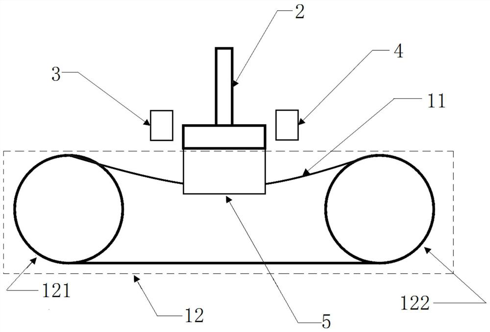
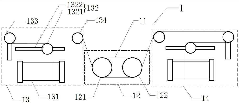
[0038] Such as figure 2 and image 3 As shown, a multi-wire cutting machine wire bow height automatic adjustment control system includes a multi-wire cutting machine 1, a feed table 2, a left sensor 3, a right sensor 4 and a controller; the feed table 2 is installed on Above the multi-wire cutting machine 1 and facing the cutting part of the multi-wire cutting machine 1, the left sensor 3 and the right sensor 4 are respectively installed on the left and right sides of the feed table 2 and used For detecting the wire bow height of the cutting part; both the left sensor 3 and the right sensor 4 are electrically connected to the input end of the controller, and the output end of the controller is electrically connected...


PUM


Abstract

The invention relates to a multi-wire sawing machine wire bow height automatic adjustment control system and method. The multi-wire sawing machine wire bow height automatic adjustment control system comprises a multi-wire sawing machine, a feeding workbench, a left sensor, a right sensor and a controller; the feeding workbench is installed above the multi-wire sawing machine and right faces a sawing part of the multi-wire sawing machine, and the left sensor and the right sensor are installed on the left side and the right side of the feeding workbench respectively. and the left sensor and the right sensor are both electrically connected with the input end of the controller, and the output end of the controller is electrically connected with the feeding workbench. The left sensor and the right sensor are used for detecting the real-time wire bow height of the multi-wire sawing machine, the controller adjusts the feeding speed of the feeding workbench according to the real-time wire bow height detected by the left sensor or/and the right sensor so as to automatically adjust and control the wire bow height of the multi-wire sawing machine, the sample trial-manufacturing cost can be reduced, the consistency of batch production is improved, the cost of batch production consumables is reduced, the labor cost is reduced, human errors are avoided, and the production efficiency is improved.

Description

technical field [0001] The invention relates to the field of multi-wire cutting machines, in particular to a control system and method for automatically adjusting the bow height of a multi-wire cutting machine. Background technique [0002] The adjustment of the cutting parameters of the multi-wire cutting machine directly affects whether the high-quality products can be cut efficiently. One of the cores of cutting parameter control is the wire bow height during cutting, and the expected wire bow height of the same material and the same specification material It is basically confirmed that the current multi-wire cutting machine on the market realizes the control of the height of the wire bow through manual segmental cutting. However, due to the different hardness, shape, and specifications of the cutting materials, when cutting a new specification material Existing schemes must adopt such figure 1 Cutting according to the flow shown, which involves the complicated process o...

Claims


Application Information

Patent Timeline
IPC IPC(8): B24B27/06B24B27/02B24B47/20B24B49/00
CPCB24B27/02B24B27/0633B24B27/0675B24B47/20B24B49/00B24B49/006
Inventor 周浙天杨合跃包昉戴永高戴力夏风
Owner PHASE MOTION CONTROL SOLUTION WUHAN CO LTD
Why Eureka
Try Eureka