Supporting base capable of being controlled and automatically moving in grinding machine

A technology for automatically moving and supporting the base, which is applied to the parts of the grinding machine tool, the grinding machine bed, the grinding workpiece support, etc., which can solve the problems of inability to automatically move the workpiece, high professionalism in operation, and high manufacturing cost, and achieve reduction Effects of manual operation, reduction of manufacturing cost, and simplification of the operation process

Inactive Publication Date: 2021-04-06
上饶市客络超商贸有限公司
View PDF0 Cites 0 Cited by
  • Summary
  • Abstract
  • Description
  • Claims
  • Application Information

AI Technical Summary

Problems solved by technology

[0002] Grinding is a mechanical processing method for removing materials. It refers to a processing method that uses abrasives and abrasive tools to remove excess material on a workpiece. Grinding is one of the most widely used methods of material removal. The cutting process of the workpiece surface, and the grinding process needs to be realized by a grinding machine. A grinding machine is a machine tool that uses abrasive tools to grind the workpiece surface. Most grinding machines use high-speed rotating grinding wheels for grinding. The existing grinding machines need Control the plane movement of the workpiece to realize the grinding of the workpiece. It cannot move the workpiece automatically and requires manual operation. For CNC grinding machines, the manufacturing cost is too high, and the operation is highly specialized and complicated.

Method used


Image

  • Supporting base capable of being controlled and automatically moving in grinding machine
  • Supporting base capable of being controlled and automatically moving in grinding machine
  • Supporting base capable of being controlled and automatically moving in grinding machine

Examples


Embodiment Construction

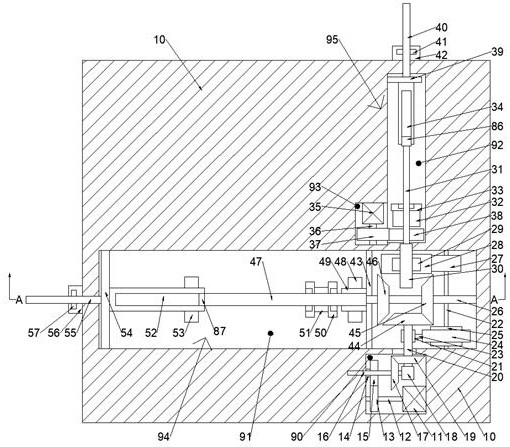
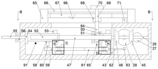
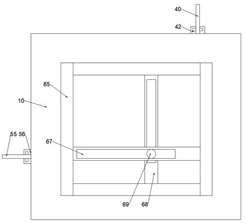
[0021] Combine below Figure 1-5 The present invention is described in detail, wherein, for the convenience of description, the orientations mentioned below are defined as follows: figure 1 The up, down, left, right, front and back directions of the projection relationship itself are the same.

[0022] A controllable and automatically movable support base in a grinding machine of the device of the present invention includes a body 10, a power chamber 90 is provided on the lower side of the body 10, and a transverse chamber 91 is provided on the upper side of the power chamber 90. A longitudinal cavity 92 is provided on the upper side of the cavity 91, and a resetting cavity 93 is provided on the left side of the longitudinal cavity 92. The front side of the body 10 is fixed with four fixed side plates 65 surrounded by a rectangle, and the front side of the fixed side plate 65 is A fixed top plate 66 is fixed on the side, and a transverse device 94 for controlling lateral move...


PUM


Abstract

The invention discloses a supporting base capable of being controlled and automatically moving in a grinding machine. The supporting base comprises a machine body, a power cavity is formed in the lower side of the machine body, a transverse cavity is formed in the upper side of the power cavity, a longitudinal cavity is formed in the upper side of the transverse cavity, a reset cavity is formed in the left side of the longitudinal cavity, four fixed side plates defining a rectangle are fixedly arranged on the front side face of the machine body, a fixed top plate is fixedly arranged on the front sides of the fixed side plates, a transverse device for controlling transverse movement is arranged in the transverse cavity and comprises a fixing plate fixedly installed in the transverse cavity, a longitudinal device for controlling longitudinal movement is arranged in the longitudinal cavity, and a moving device capable of moving automatically is arranged on the front side of the machine body. Movement of a workpiece on the grinding machine can be automatically and rapidly achieved so that the equipment can be matched with grinding machining of the grinding machine, due to a mechanical structure, the manufacturing cost of the grinding machine is reduced, manual operation of the grinding machine is further reduced, and simplification of the grinding operation process and reliability and stability of equipment operation are achieved.

Description

technical field [0001] The invention relates to the related fields of grinding devices or equipment, in particular to a controllable and automatically movable support base in a grinding machine. Background technique [0002] Grinding is a mechanical processing method for removing materials. It refers to a processing method that uses abrasives and abrasive tools to remove excess material on a workpiece. Grinding is one of the most widely used methods of material removal. The cutting process of the workpiece surface, and the grinding process needs to be realized by a grinding machine. A grinding machine is a machine tool that uses abrasive tools to grind the workpiece surface. Most grinding machines use high-speed rotating grinding wheels for grinding. The existing grinding machines need Control the plane movement of the workpiece to realize the grinding of the workpiece. It cannot move the workpiece automatically and requires manual operation. For CNC grinding machines, the m...

Claims


Application Information

Patent Timeline
Patent Type & Authority Applications(China)
IPC IPC(8): B24B41/02B24B41/06B24B41/00
CPCB24B41/00B24B41/02B24B41/06
Inventor 刘金率
Owner 上饶市客络超商贸有限公司
Why Eureka
Try Eureka