Oil-containing emulsified wastewater treatment device

A treatment device and emulsified wastewater technology, applied in water/sewage treatment, heating water/sewage treatment, water/sewage treatment equipment, etc., can solve problems such as inability to achieve heat transfer, increase equipment power loss, and affect heat transfer , to achieve the effect of preventing the emulsion from adhering to the inner wall, increasing the contact strength, and enhancing the contact strength

Active Publication Date: 2021-04-06
烟台垚磊信息技术有限公司
View PDF5 Cites 0 Cited by
  • Summary
  • Abstract
  • Description
  • Claims
  • Application Information

AI Technical Summary

Problems solved by technology

[0004] However, in the actual use process, in order to speed up the oil emulsification and demulsification treatment, a heating device is added outside the demulsification tank, so that the oil emulsion waste liquid can be demulsified faster through the external heat, but it will increase its equipment at the same time. At the same time, the heating equipment installed on the outer wall cannot achieve uniform heat transfer, which leads to large differences in the temperature of the oil emulsion in various places during the demulsification process, resulting in a decrease in the demulsification efficiency
[0005] At the same time, the emulsion containing oily waste liquid will adhere to the inner wall of the demulsification tank, which not only affects the heat transfer, but also affects the waste liquid contained in a single demulsification. At the same time, The long-term aggregated emulsion will harden, which will increase the load of subsequent demulsification, resulting in a significant reduction in the efficiency of demulsification

Method used


Image

  • Oil-containing emulsified wastewater treatment device
  • Oil-containing emulsified wastewater treatment device
  • Oil-containing emulsified wastewater treatment device

Examples


Embodiment Construction

[0026]Next, the technical solutions in the embodiments of the present invention will be apparent from the embodiment of the present invention, and it is clearly described, and it is understood that the described embodiments are merely embodiments of the present invention, not all of the embodiments. Based on the embodiments of the present invention, there are all other embodiments obtained without making creative labor without making creative labor premises.

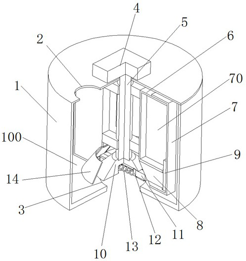
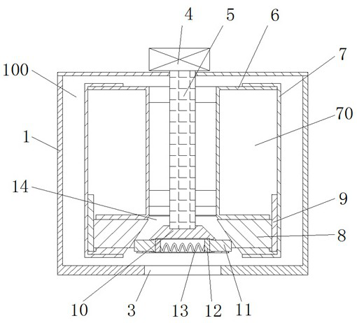
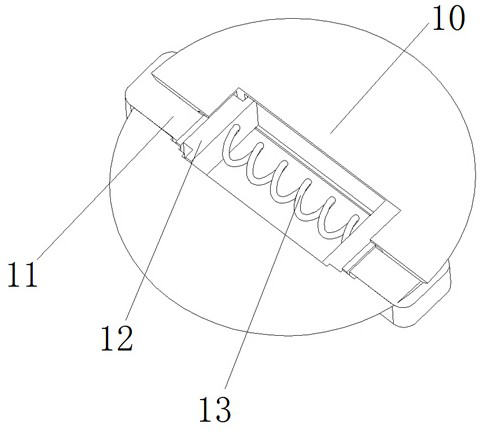
[0027]SeeFigure 1-6An oil-containing emulsified wastewater treatment device includes a broken milky tank 1, and the inner wall of the broken poker 1 is opened with a broken mammine cavity 100, and the top of the broken cage 1 is opened, and the bottom portion of the breast milk box 1 is opened. The liquid opening 3, and the central portion of the cutting of the milk box 1 is fixedly mounted, the drive motor 4 is mounted, and the drive shaft 5 is fixedly mounted, the side wall activity of the drive shaft 5 is mounted, and the driv...


PUM


Abstract

The invention relates to the technical field related to wastewater treatment technologies, and discloses an oil-containing emulsified wastewater treatment device which comprises a demulsification box, a demulsification cavity is formed in the inner wall of the demulsification box, a liquid inlet is formed in the top of the demulsification box, a liquid outlet is formed in the bottom of the demulsification box, and a driving motor is fixedly mounted in the middle of the top end of the demulsification box. A driving shaft is fixedly mounted on a rotating shaft of the driving motor, and driving blades are movably mounted on the side wall of the driving shaft. The driving blades are movably mounted on the side wall of the driving shaft, and meanwhile, heat is generated through friction between the heating block at the bottom end of the driving shaft and the heat transfer blocks on the driving blades, so that the temperature of wastewater in the demulsification cavity is increased; and through friction between the heat transfer block and the heating block, the driving blades synchronously rotate along with the heating block, so that stirring demulsification and self-heating are carried out to increase the temperature of the wastewater, and the purposes of low energy consumption and high efficiency demulsification are achieved.

Description

Technical field[0001]The present invention relates to the chemical art of wastewater treatment technology, and is specifically an oil-containing emulsified wastewater treatment device.Background technique[0002]Oil-containing emulsified wastewater is an important pollutant produced by refinery, woolen mills, chemical and machinery processing industries. Among them, due to a large amount of emulsifying oil in its wastewater, if it is not treated, it is directly used as wastewater, and the waste liquid is discharged. A large pollution caused.[0003]Existing oil emulsion wastewater is treated in the process, its workflow is mainly: through the crushing apparatus through the crushing device, after filtering, the filtration of the wastewater is achieved by multiple filtration.[0004]However, in the actual use process, in order to speed up the oil emulsifying, the heating device is added to the outside of the breast milk, thereby causing the oil milk waste liquid to increase the emulsion, bu...

Claims


Application Information

Patent Timeline
Patent Type & Authority Applications(China)
IPC IPC(8): C02F1/40C02F1/02
CPCC02F1/02C02F1/40C02F2201/002C02F2201/004C02F2303/14
Inventor 王小娟王从未祁振高丽娟苏志慧李苹
Owner 烟台垚磊信息技术有限公司
Why Eureka
Try Eureka