A treatment device for oily emulsified wastewater

A treatment device and emulsified wastewater technology, which is applied in water/sewage treatment, heating water/sewage treatment, water/sewage treatment equipment, etc., can solve the problems of inability to realize heat transfer, increase equipment power loss, and large temperature difference between oil and milk, etc. problems, to achieve the effect of preventing the emulsion from adhering to the inner wall, enhancing the contact strength, and reducing the temperature difference

Active Publication Date: 2021-05-07
烟台垚磊信息技术有限公司
View PDF5 Cites 0 Cited by
  • Summary
  • Abstract
  • Description
  • Claims
  • Application Information

AI Technical Summary

Problems solved by technology

[0004] However, in the actual use process, in order to speed up the oil emulsification and demulsification treatment, a heating device is added outside the demulsification tank, so that the oil emulsion waste liquid can be demulsified faster through the external heat, but it will increase its equipment at the same time. At the same time, the heating equipment installed on the outer wall cannot achieve uniform heat transfer, which leads to large differences in the temperature of the oil emulsion in various places during the demulsification process, resulting in a decrease in the demulsification efficiency
[0005] At the same time, the emulsion containing oily waste liquid will adhere to the inner wall of the demulsification tank, which not only affects the heat transfer, but also affects the waste liquid contained in a single demulsification. At the same time, The long-term aggregated emulsion will harden, which will increase the load of subsequent demulsification, resulting in a significant reduction in the efficiency of demulsification

Method used


Image

  • A treatment device for oily emulsified wastewater
  • A treatment device for oily emulsified wastewater
  • A treatment device for oily emulsified wastewater

Examples


Embodiment Construction

[0026] The following will clearly and completely describe the technical solutions in the embodiments of the present invention with reference to the accompanying drawings in the embodiments of the present invention. Obviously, the described embodiments are only some, not all, embodiments of the present invention. Based on the embodiments of the present invention, all other embodiments obtained by persons of ordinary skill in the art without making creative efforts belong to the protection scope of the present invention.

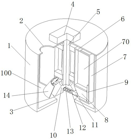
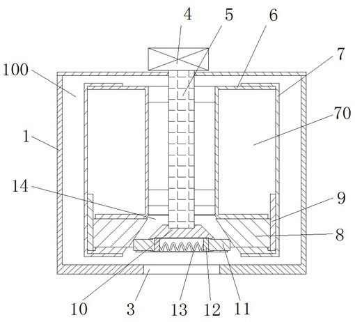
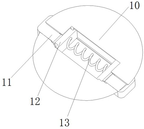
[0027] see Figure 1-6 , an oil-containing emulsified wastewater treatment device, comprising a demulsification tank 1, an demulsification cavity 100 is provided on the inner wall of the demulsification tank 1, and a liquid inlet 2 is provided on the top of the demulsification tank 1, and a demulsification chamber 100 is provided on the bottom of the demulsification tank 1 A liquid outlet 3, and a drive motor 4 is fixedly installed in the middle of the top of ...


PUM


Abstract

The invention relates to the technical field of waste water treatment technology, and discloses an oil-containing emulsified waste water treatment device, comprising a demulsification tank, a demulsification cavity is opened on the inner wall of the demulsification tank, and a liquid inlet is opened on the top of the demulsification tank , the bottom of the demulsification box is provided with a liquid outlet, and the middle part of the top of the demulsification box is fixedly installed with a drive motor, the rotating shaft of the drive motor is fixedly installed with a drive shaft, and the side wall of the drive shaft is movably installed with drive blades. In the present invention, drive blades are movably installed on the side wall of the drive shaft, and at the same time, heat is generated by friction between the heat generating block at the bottom end of the drive shaft and the heat transfer block on the drive blade, so as to increase the temperature of the waste water in the demulsification chamber. At the same time, The friction between the heat transfer block and the heat generation block also makes the driving blades rotate synchronously with the heat generation block, and then perform agitation and demulsification and self-heating to increase the temperature of the wastewater, so as to achieve the purpose of low energy consumption and high efficiency demulsification.

Description

technical field [0001] The invention relates to the related technical field of wastewater treatment technology, in particular to an oil-containing emulsified wastewater treatment device. Background technique [0002] Oily emulsified wastewater is an important pollutant produced by oil refineries, woolen mills, chemical and mechanical processing industries. Among them, because the wastewater contains a large amount of emulsified oil, if it is not treated, it will be discharged directly as wastewater or waste liquid, which will affect the ecological environment. cause a lot of pollution. [0003] In the process of treating the existing oily emulsified wastewater, its work flow is mainly as follows: the wastewater containing oily liquid is demulsified through a crushing device, and then, the wastewater is filtered and treated through multiple filtrations. [0004] However, in the actual use process, in order to speed up the oil emulsification and demulsification treatment, a h...

Claims


Application Information

Patent Timeline
Patent Type & Authority Patents(China)
IPC IPC(8): C02F1/40C02F1/02
CPCC02F1/02C02F1/40C02F2201/002C02F2201/004C02F2303/14
Inventor 王小娟王从未祁振高丽娟苏志慧李苹
Owner 烟台垚磊信息技术有限公司
Why Eureka
Try Eureka