Automatic flushing structure of mechanical seal of double suction pump

An automatic flushing, double-suction pump technology, applied in the directions of machines/engines, pumps, pump components, etc., can solve problems such as pipe bursting, increase labor hours and costs, increase equipment space, and reduce production costs, processing convenience, and structure. compact effect

Pending Publication Date: 2021-04-06
SHANGHAI KAIQUAN PUMP IND GROUP
View PDF0 Cites 0 Cited by
  • Summary
  • Abstract
  • Description
  • Claims
  • Application Information

AI Technical Summary

Problems solved by technology

[0003] from figure 2 It can be seen that the flushing structure of the mechanical seal of the double-suction pump mostly uses external pipes to flush and lubricate the mechanical seal. Welding is easy to produce water leakage points. Most of the external pipes are connected by elbows and straight pipes, which increases the possibility of leakage. The external pipes increase the space occupied by the equipment, increase man-hours and costs, and affect the overall appearance of the pump.
When the double-suction pump transports high-temperature, high-pressure, and high-concentration liquids, the external pipeline is prone to blockage, which may cause a pipe burst, causing certain safety accidents. Under this working condition, the external pipeline cannot properly flush and lubricate the mechanical seal

Method used


Image

  • Automatic flushing structure of mechanical seal of double suction pump
  • Automatic flushing structure of mechanical seal of double suction pump
  • Automatic flushing structure of mechanical seal of double suction pump

Examples


Embodiment Construction

[0016] The preferred embodiments of the present invention are given below in conjunction with the accompanying drawings to describe the technical solution of the present invention in detail.

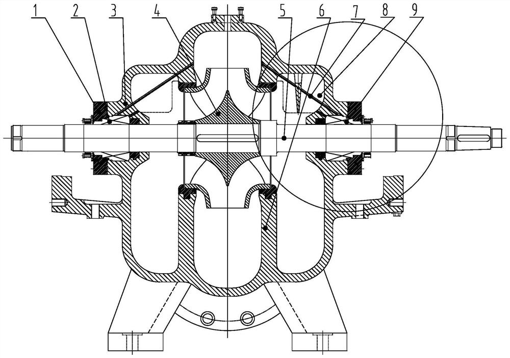
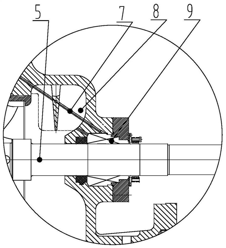
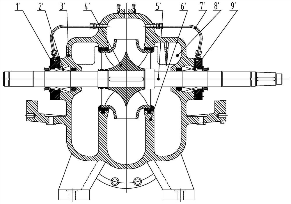
[0017] figure 2 It is a schematic diagram of the automatic flushing structure of the common double-suction pump mechanical seal at present. Such as figure 2 Shown: The common double-suction pump mechanical seal automatic flushing structure includes the seal flushing part, the seal flushing part includes the seal flushing pipeline and the seal flushing pipeline accessories matched with the seal flushing pipeline; the seal flushing pipeline is led out from both ends of the pump cover , the two ends connected to the flushing hole of the machine seal gland or the flushing hole reserved for packing in the pump cover.

[0018] From figure 2 It can be seen that the flushing structure of the mechanical seal of the double-suction pump mostly uses external pipes to flush and lubricate the mecha...


PUM


Abstract

The invention relates to an automatic flushing structure of a mechanical seal of a double suction pump. The automatic flushing structure is arranged in the double suction pump and comprises a left sealing flushing hole and a right sealing flushing hole which are located in a pump cover, wherein the sealing flushing holes are led out from the two ends of the upper end of the pump cover respectively and penetrate through a water suction chamber partition plate, and the two led-out ends of the sealing flushing holes are connected to a mechanical seal flushing cavity between the pump cover and a shaft. In the design process, a hole is drilled in the pump cover and directly faces a joint of a movable ring and a static ring of the mechanical seal, and in order to facilitate machining, the hole can deviate from the shaft by any angle, but the hole is guaranteed to be aligned with the joint of the movable ring and the static ring. The size of the hole diameter is determined according to the size of the mechanical seal of the designed pump. Through the high-pressure characteristic of liquid in a pump cavity, the mechanical seal is automatically flushed and lubricated through drilling, the structure is convenient to machine and compact, and the production cost is reduced. The overall strength of the pump cover is not damaged, an external pipeline capable of increasing the occupied space of equipment is not adopted, and the whole pump is attractive.

Description

technical field [0001] The invention relates to an automatic flushing structure, in particular to an automatic flushing structure for a double-suction pump mechanical seal with convenient processing, compact structure, reduced production cost, no damage to the overall strength of the pump cover, and no space-occupied external pipes. Background technique [0002] figure 2 It is a schematic diagram of the automatic flushing structure of the common double-suction pump mechanical seal at present. Such as figure 2 Shown: The common double-suction pump mechanical seal automatic flushing structure includes the seal flushing part, the seal flushing part includes the seal flushing pipeline and the seal flushing pipeline accessories matched with the seal flushing pipeline; the seal flushing pipeline is led out from both ends of the pump cover , the two ends connected to the flushing hole of the machine seal gland or the flushing hole reserved for packing in the pump cover. [0003]...

Claims


Application Information

Patent Timeline
Patent Type & Authority Applications(China)
IPC IPC(8): F04D1/00F04D29/70F04D29/42F04D29/12F04D29/06
CPCF04D1/006F04D29/061F04D29/126F04D29/426F04D29/708
Inventor 朱艳萍
Owner SHANGHAI KAIQUAN PUMP IND GROUP
Why Eureka
Try Eureka