
Novel millimeter-wave radar signal processing method

A millimeter-wave radar and signal processing technology, applied in the field of radar, can solve the problems of increasing radar volume, unable to take into account the angular resolution, and increasing cost at the same time.

Pending Publication Date: 2021-04-06
北京理工睿行电子科技有限公司 +1
View PDF0 Cites 4 Cited by
  • Summary
  • Abstract
  • Description
  • Claims
  • Application Information

AI Technical Summary

Problems solved by technology

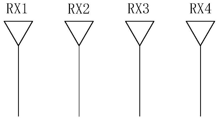
[0005] Although the MIMO technology doubles the number of antenna arrays, every time a transmitting antenna is added, the virtual array will double the number of receiving antennas, which effectively improves the angle measurement resolution to a certain extent, but the increase in the number of antennas causes the radar volume to increase. large, costly
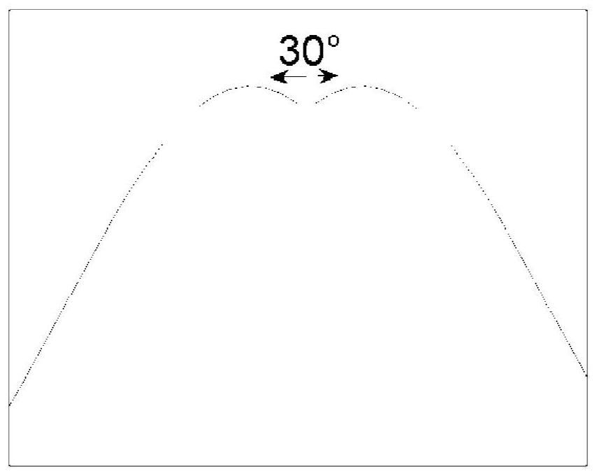
And in the case of a limited number of antennas, the angular resolution increases with the increase of the antenna spacing, but the field of view FOV decreases accordingly, and it is impossible to take into account the two indicators of angular resolution and FOV at the same time

Method used


Image

  • Novel millimeter-wave radar signal processing method
  • Novel millimeter-wave radar signal processing method
  • Novel millimeter-wave radar signal processing method

Examples


Embodiment Construction

[0024] Various exemplary embodiments, features, and aspects of the present disclosure will be described in detail below with reference to the accompanying drawings. The same reference numbers in the figures indicate functionally identical or similar elements. While various aspects of the embodiments are shown in drawings, the drawings are not necessarily drawn to scale unless specifically indicated.

[0025] The word "exemplary" is used exclusively herein to mean "serving as an example, embodiment, or illustration." Any embodiment described herein as "exemplary" is not necessarily to be construed as superior or better than other embodiments.

[0026] In addition, in order to better illustrate the present disclosure, numerous specific details are given in the following specific implementation manners. It will be understood by those skilled in the art that the present disclosure may be practiced without some of the specific details. In some instances, methods, means, componen...


PUM


Abstract

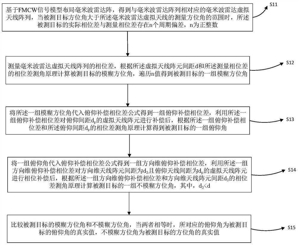
The invention provides a radar signal processing method which comprises the steps: arranging a millimeter wave radar virtual antenna array, wherein periodic deviation exists between the actual phase difference and the measurement phase difference when the azimuth angle is larger than the measurement azimuth angle of the virtual antenna; measuring the phase difference, and calculating a fuzzy azimuth angle according to a phase method angle measurement principle; substituting the fuzzy azimuth angle into a pitch compensation phase difference formula to obtain a pitch compensation phase difference, compensating the antenna array element by utilizing the pitch compensation phase difference, and then obtaining a pitch angle according to the phase method angle measurement principle; substituting the pitch angle into a pitch compensation phase difference formula to obtain a direction-dimensional pitch compensation phase difference, performing phase compensation on the antenna array element by utilizing the direction-dimensional pitch compensation phase difference, and then obtaining an unambiguous azimuth angle according to the phase method angle measurement principle; and comparing the fuzzy azimuth angle with the non-fuzzy azimuth angle, and obtaining a true value of the pitch angle when the two angles are equal. The large FOV and the high angle resolution can be achieved without additionally increasing the number of antennas, and the contradiction between the angle resolution and the azimuth angle range is effectively reconciled.

Description

technical field [0001] The disclosure belongs to the technical field of radar, and in particular relates to a novel millimeter-wave radar signal processing method. Background technique [0002] In the design of vehicle radar, the phase angle measurement method is usually used as the detection method of the azimuth angle of the measured target. Use several antennas in different spatial positions to obtain the phases of the echoes of the measured target, and the phase difference is generated due to the existence of the echo path difference ΔR (ΔR=dsinθ), and the azimuth angle of the measured target is calculated by the phase difference (according to ). Theoretically speaking, if the phase difference of each echo is known, the azimuth angle of the measured target can be accurately calculated. However, during the measurement process, the phase difference is limited between (-π, π), and the actual value of the phase difference There is an offset of several cycles between the m...

Claims


Application Information

Patent Timeline
IPC IPC(8): G01S13/60G01S7/35
CPCG01S13/60G01S7/354
Inventor 金烨安清儒刘建虎陈桥梁思嘉常维国王瑜琪龙佳敏连红飞陈思佳李乐
Owner 北京理工睿行电子科技有限公司
Learn More