Optical fiber welding method

A technology of optical fiber fusion and optical fiber, which is applied in the field of optical fiber fusion, can solve the problems of poor quality of optical fiber fusion, and achieve the effect of reducing fusion error, less loss, and large signal transmission

Pending Publication Date: 2021-04-06
无锡锐科光纤激光技术有限责任公司
View PDF3 Cites 0 Cited by
  • Summary
  • Abstract
  • Description
  • Claims
  • Application Information

AI Technical Summary

Problems solved by technology

[0003] The invention provides an optical fiber fusion splicing method to solve the problem of poor fusion splicing quality between optical fibers with different core diameters and / or different geometric structures in the prior art

Method used


Image

  • Optical fiber welding method
  • Optical fiber welding method

Examples


Embodiment Construction

[0029] In order to make the purpose, technical solutions and advantages of the present invention clearer, the technical solutions in the present invention will be clearly and completely described below in conjunction with the accompanying drawings in the present invention. Obviously, the described embodiments are part of the embodiments of the present invention , but not all examples. Based on the embodiments of the present invention, all other embodiments obtained by persons of ordinary skill in the art without creative efforts fall within the protection scope of the present invention.

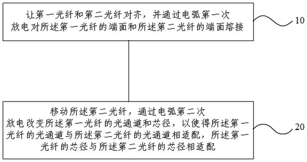
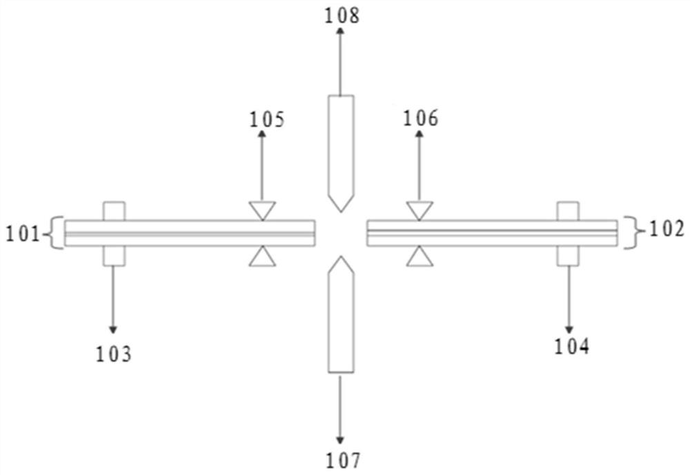
[0030] Combine below Figure 1 to Figure 2 The optical fiber fusion splicing method of the present invention will be described.

[0031] The following describes the optical fiber fusion splicing system used in the optical fiber fusion splicing method of the embodiment of the present invention, as figure 2 As shown, the optical fiber fusion splicing system includes two symmetrically arrange...


PUM


Abstract

The invention provides an optical fiber welding method, which comprises the following steps of: aligning a first optical fiber and a second optical fiber, and welding the end surface of the first optical fiber and the end surface of the second optical fiber through arc first discharge; and moving the second optical fiber, and changing the optical channel and the core diameter of the first optical fiber through electric arc secondary discharging, so that the optical channel of the first optical fiber is matched with the optical channel of the second optical fiber, and the core diameter of the first optical fiber is matched with the core diameter of the second optical fiber. According to the optical fiber fusion splicing method provided by the invention, accompanying discharge is added, that is, after fusion splicing is completed, a section of optical fiber of the fiber core with a small size is discharged again through the optical fiber fusion splicing system, the core diameter of the fiber core is properly enlarged, and the optical channel of pump light is widened, so that the fiber core can be better matched with the fiber core with a large fusion splicing size; and therefore, the effect of reducing the welding error is achieved, and the problem of high light temperature of the missing cladding caused by welding deviation is reduced.

Description

technical field [0001] The invention relates to the technical field of optical fiber and cable, in particular to an optical fiber fusion splicing method. Background technique [0002] In the production process of conventional pulsed fiber lasers, 20 / 250 passive fibers and 30 / 250 doped active fibers are often spliced. Since the core sizes of the two optical fibers are different, and the doping concentration media of the two fibers are also different, if the conventional fusion splicing method is adopted, that is, the two are directly fused together, it will inevitably lead to loss at the splice point. Large; and the fusion point is easy to leak light to the cladding, resulting in high temperature on the cladding dispensing surface. Over time, the heat accumulates in the glue layer, which is easy to burn out the glue layer, thereby reducing the welding quality of the pulsed fiber laser. Contents of the invention [0003] The invention provides an optical fiber fusion splici...

Claims


Application Information

Patent Timeline
Patent Type & Authority Applications(China)
IPC IPC(8): G02B6/255
CPCG02B6/2551
Inventor 徐贝贝庞亚维叶鹏王志源
Owner 无锡锐科光纤激光技术有限责任公司
Why Eureka
Try Eureka