Large-buried-depth tunnel top vertical shaft backfilling load-reducing structure and construction method thereof

A construction method and technology for shafts, which are applied to shaft equipment, tunnels, fillings, etc., can solve the problems of difficult reinforcement of underlying tunnels, heavy backfilling structure, and easy collapse of wellbore holes, etc. Good performance, significant effect of preventing water leakage

Active Publication Date: 2021-04-09
LANZHOU RAILWAY SURVEY & DESIGN INST
View PDF5 Cites 1 Cited by
  • Summary
  • Abstract
  • Description
  • Claims
  • Application Information

AI Technical Summary

Problems solved by technology

[0009] The purpose of the present invention is to provide a backfill and load-reduction structure for the top shaft of a large buried deep tunnel to solve the problem that the existing backfill structure is heavy, easy to accumulate water, the wellbore is abandoned for a long time and the hole is easy to collapse, the underlying tunnel is difficult to reinforce, and there is water leakage, Risk issues such as cracking, crushing and landslides, filling the technical gap in this field

Method used


Image

  • Large-buried-depth tunnel top vertical shaft backfilling load-reducing structure and construction method thereof
  • Large-buried-depth tunnel top vertical shaft backfilling load-reducing structure and construction method thereof
  • Large-buried-depth tunnel top vertical shaft backfilling load-reducing structure and construction method thereof

Examples


Embodiment Construction

[0034] The present invention will be described in further detail below in conjunction with the accompanying drawings and specific embodiments.

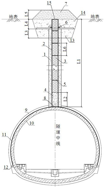
[0035] Such as figure 1 As shown, the top shaft backfill load reduction structure of the present invention includes the existing shaft 1, the bottom of the shaft 1 is provided with a bottom sealing plate 8, and the bottom sealing plate 8 is an arc-shaped plate, and its concave surface is in line with the initial support 9 of the tunnel. The outer edges match; the shaft 1 is provided with a protective tube 2 of height L1 that closely fits the inner wall of the shaft 1; the top of the protective tube 2 extends out of the shaft 1, and the top surface of the protective tube 2 is flush with the ground surface; The protective tube 2 is formed by successively connecting a plurality of cylindrical steel casings with an inner diameter of D, and two adjacent steel casings are threaded or welded; the bottom end of the protective tube 2 is in con...


PUM


Abstract

The invention discloses a large-buried-depth tunnel top vertical shaft backfilling load-reducing structure and a construction method thereof. The structure comprises a protection pipe which is arranged in a vertical shaft, wherein the top end of the protection pipe extends out of the vertical shaft, and a bottom sealing layer and a plurality of filling layers are arranged in the protection pipe; foldable supports are arranged between the adjacent filling layers, a base, a locking opening supporting beam and an outer wrapping layer are arranged outside the vertical shaft, and the parts, extending out of the vertical shaft, of the locking opening supporting beam and the protection pipe are located in the outer wrapping layer; and a soil sealing layer is arranged on the outer wrapping layer. A plurality of sections of steel protection cylinders are hoisted into the vertical shaft to form the protection pipe, the base is poured, the locking opening supporting beam is erected, the outer wrapping layer is poured, drainage blind pipes are densely arranged, and a secondary lining is poured; concrete is pumped into the protection pipe, the bottom sealing layer is formed through vibration and compaction, the bottom sealing layer is alternately provided with the filling layers and the foldable supports until the top surfaces of the finally-formed filling layers are flush with the top surface of the protection pipe, and a well top sealing plate is welded to the top surface of the protection pipe; and the soil sealing layer is piled on the outer wrapping layer, and the large-buried-depth tunnel top vertical shaft backfilling load-reducing structure is built. The load-reducing structure can effectively protect the safety of an underlying tunnel, and the technical blank is filled up.

Description

technical field [0001] The invention belongs to the technical field of tunnels and underground engineering, and relates to a backfill load-reduction structure for a vertical shaft at the top of a deep tunnel; the invention also relates to a construction method of the backfill load-reduction structure. Background technique [0002] During the construction of long and deep tunnels, in order to meet the requirements of construction period, ventilation, smoke exhaust and cooling, auxiliary construction shafts are generally set up on the side or top of the tunnel. If a vertical shaft is installed on one side of the tunnel, it is necessary to set up a connecting channel to connect with the main tunnel, and there are many process changes. Through-hole, high slag discharge efficiency, which is conducive to rapid ventilation, smoke exhaust and cooling in the cave, and the effect is remarkable. However, after the shaft is abandoned in the later stage, it is difficult to deal with larg...

Claims


Application Information

Patent Timeline
Patent Type & Authority Applications(China)
IPC IPC(8): E21F15/00E21F16/02E21D11/00E21D8/00
CPCE21F15/00E21F16/02E21D11/003E21D8/00Y02E10/20
Inventor 张威王君顺李明姬云平李守刚赵录学马玉春王伯龙祁卫华兰建刘志诚徐同启霍春辉崔建龙王杰
Owner LANZHOU RAILWAY SURVEY & DESIGN INST
Why Eureka
Try Eureka