
Proximity sensor circuit and distance detection method

A technology of proximity sensors and circuits, applied in the field of proximity sensors, can solve problems such as product performance changes, low efficiency, and labor

Pending Publication Date: 2021-04-09
上海索迪龙自动化股份有限公司
View PDF9 Cites 2 Cited by
  • Summary
  • Abstract
  • Description
  • Claims
  • Application Information

AI Technical Summary

Problems solved by technology

[0003] At present, the traditional production process of proximity sensors is as follows: circuit board patch processing - welding discrete devices - circuit board debugging - assembly - glue filling - aging test; Influenced by factors such as the external environment, the consistency of the product is poor, and the detection accuracy is not high. After the circuit board is debugged, it needs to be filled with glue and assembled. Adjustment, resulting in the loss of finished product yield; and because each product needs to be debugged before assembly, it requires a lot of labor, low efficiency and slow speed. With the increase of labor costs in recent years and the improvement of end customers' performance requirements for products, There are still a large number of products that need to be miniaturized, and traditional LC proximity sensors are increasingly unable to meet the needs of terminals

Method used


Image

  • Proximity sensor circuit and distance detection method
  • Proximity sensor circuit and distance detection method
  • Proximity sensor circuit and distance detection method

Examples


Embodiment Construction

[0026] In order to make the purpose, technical solutions and advantages of the embodiments of the present invention clearer, the technical solutions in the embodiments of the present invention will be clearly and completely described below in conjunction with the drawings in the embodiments of the present invention. Obviously, the described embodiments It is a part of the embodiments of the present invention, rather than all embodiments; based on the embodiments of the present invention, all other embodiments obtained by those of ordinary skill in the art without creative work, all belong to the protection scope of the present invention .

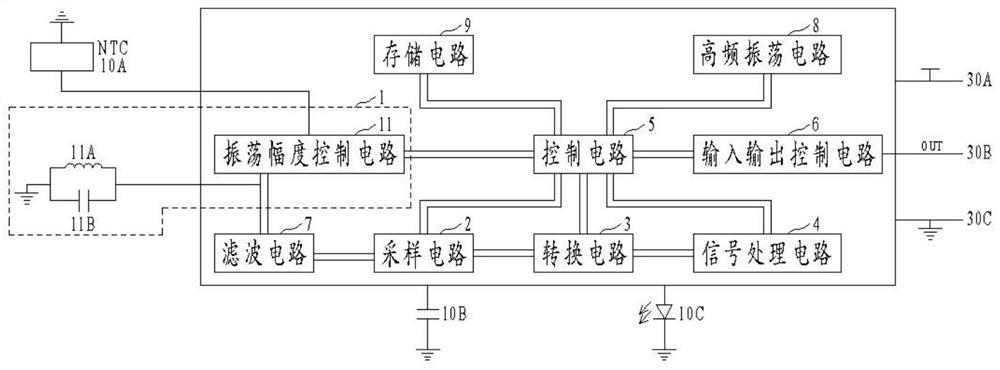
[0027] A complete proximity switch sensor generally includes: an oscillation detection part composed of an external coil 11A (L) and a capacitor 11B (C) and the built-in circuit of the present invention; Auxiliary circuits composed of discrete devices 10B, etc.; and shells and wires (30A, 30B, 30C), some peripheral devices such as power sup...


PUM


Abstract

The invention discloses a proximity sensor circuit and a distance detection method. The proximity sensor circuit comprises an LC oscillation circuit which is used for generating an oscillation signal with a specific frequency when a metal body is detected to be close to or far away from a coil; a sampling circuit which is used for collecting the oscillation signal generated by the LC oscillation circuit within a threshold voltage; a conversion circuit which is used for converting the oscillation signal acquired by the sampling circuit into a high-frequency pulse signal; a signal processing circuit which is used for carrying out operation processing on the high-frequency pulse signal generated by the conversion circuit and then executing different operations according to an instruction of a control circuit; the control circuit which is used for receiving a circuit external control instruction; and an input and output control circuit which is used for outputting the data sent by the control circuit through an output driving end OUT. Manual work is reduced in the aspect of machining, the yield is improved, the periphery of a product is simple, the size is small, the miniaturization requirement of customers is met, the consistency in performance is good, the precision is high, parameters can be set, the product upgrading requirement is met, and extremely high practicability is achieved.

Description

technical field [0001] The invention belongs to the technical field of proximity sensors, and in particular relates to a proximity sensor circuit and a distance detection method. Background technique [0002] LC proximity sensors are widely used in industrial equipment, automotive electronics and other fields. At present, most of these proximity sensors on the market use discrete devices or analog circuits such as general-purpose amplifiers and comparators to realize distance recognition, distance setting and other parameters. The setting is done by adjusting external devices such as external resistors or capacitors. [0003] At present, the traditional production process of proximity sensors is as follows: circuit board patch processing - welding discrete devices - circuit board debugging - assembly - glue filling - aging test; Influenced by factors such as the external environment, the consistency of the product is poor, and the detection accuracy is not high. After the c...

Claims


Application Information

Patent Timeline
IPC IPC(8): G01D5/20
CPCG01D5/20
Inventor 邓志才陈坤速
Owner 上海索迪龙自动化股份有限公司
Learn More