
Method for designing strong interference suppression beamformer under multi-target condition

A design method, the technology of the former, applied in the direction of instruments, radio wave measurement systems, systems for eliminating unnecessary waves, etc., can solve the problems of spatial proximity distribution and related sound source localization problems such as helplessness and so on

Pending Publication Date: 2021-04-09
HAIYING ENTERPRISE GROUP
View PDF0 Cites 1 Cited by
  • Summary
  • Abstract
  • Description
  • Claims
  • Application Information

AI Technical Summary

Problems solved by technology

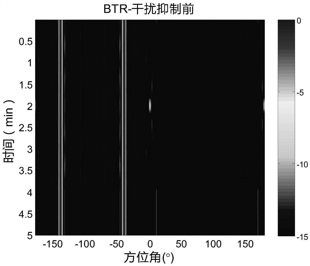
[0003] However, when performing orientation estimation in a multi-target environment, although conventional positioning methods such as conventional beamforming (CBF) and minimum variance distortion-free beamforming (MVDR) have certain spatial resolution capabilities, they are not suitable for spatial proximity distribution and correlation The localization of the sound source is helpless

Method used


Image

  • Method for designing strong interference suppression beamformer under multi-target condition
  • Method for designing strong interference suppression beamformer under multi-target condition
  • Method for designing strong interference suppression beamformer under multi-target condition

Examples


Embodiment 1

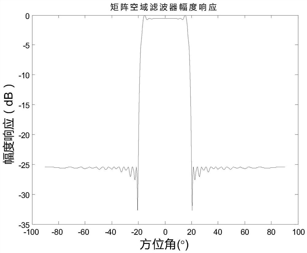
[0091] The invention specifically discloses a technical scheme of a design method of a strong interference suppression beamformer under multi-target conditions, including the following steps:

[0092] S1. Design a filter matrix G∈C M×M , so that the filter output y(t)=Gx(t), t=1,...,N has spatial filtering characteristics, where the matrix spatial filtering principle,

[0093] The following conditions should be met:

[0094] For a known arbitrary geometry matrix composed of M array elements, it is assumed that there are D(DD =[θ 1 ,...θ d …theta D ] incident on the base array, the narrowband array signal model received by these M array elements can be expressed as

[0095] x(t)=A(Θ D )s(t)+n(t) (1);

[0096] A(Θ D )=[a(θ 1 ), a(θ 2 ),…,a(θ D )] is M×D dimension array manifold matrix, s(t)=[s 1 (t),s 2 (t),...,s D (t)] T is a D×1-dimensional signal source vector, n(t) is an M×1-dimensional noise vector,

[0097] Design a filter matrix G∈C for formula (1) M×M , s...


PUM


Abstract

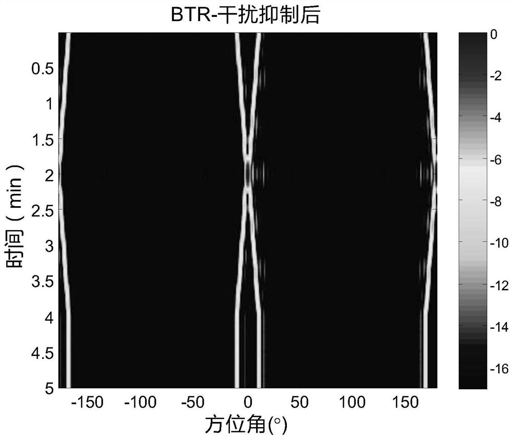
The invention belongs to the technical field of underwater acoustic equipment design and manufacturing and relates to a method for designing a strong interference suppression beamformer under a multi-target condition. The method comprises the following steps that: S1, a filtering matrix G belonging to CM*M is designed, the output y (t) of a filter is equal to Gx (t) has a spatial filtering characteristic, wherein t is equal to 1,..., N, and a matrix spatial filtering principle should satisfy one of conditions described in the descriptions of the invention; S2, a sparse super-resolution azimuth estimation algorithm is adopted; S3, spatial matrix filtering-based sparse super-resolution azimuth estimation is performed, namely, super-resolution azimuth estimation of a weak target in a strong interference environment can be realized by using spatial matrix filtering and a 1- type sparse approximate minimum variance algorithm; and S4, computer simulation and actual measurement test data verification of the algorithm are performed. The matrix filter with spatial filtering characteristics of the passband and the stop band is designed; a high-resolution sparse azimuth estimation algorithm is adopted, so that interference is effectively suppressed to the greatest extent in a signal processing process, the detection capability of a sonar on the weak target is improved, the output signal-to-noise ratio of the matrix is improved, and the remote detection capability of the sonar is enhanced.

Description

technical field [0001] The invention relates to the technical field of design and manufacture of underwater acoustic equipment, in particular to a method for designing a strong interference suppression beamformer under multi-target conditions. Background technique [0002] Super-resolution orientation estimation in strong interference environment is an important research topic in the field of sonar and other array signal processing. For example, the noise of tugboats in towed line array sonar is a strong interference source, and its existence will mask underwater targets or affect the positioning accuracy of underwater targets. Improving the target azimuth resolution ability under strong interference environment is the current research focus. Matrix filtering technology is an effective means to achieve strong interference suppression in known azimuths. Matrix filter was first proposed and used in the field of frequency filtering. Vaccaro gave the design criteria of frequen...

Claims


Application Information

Patent Timeline
Patent Type & Authority Applications(China)
IPC IPC(8): G01S7/537G01S3/86G01S3/802
CPCG01S3/802G01S3/86G01S7/537
Inventor 白云刘海嫚杨鑫陆路
Owner HAIYING ENTERPRISE GROUP
Learn More