Space laser structure

A laser and space technology, applied in the field of lasers, can solve problems affecting laser life and reliability, optical path changes, and reduce the life of optical devices, etc., to solve the impact of structural deformation, reduce the impact of structural deformation, and improve the effect of on-orbit life

Inactive Publication Date: 2021-04-09
BEIJING RES INST OF TELEMETRY +1
View PDF10 Cites 2 Cited by
  • Summary
  • Abstract
  • Description
  • Claims
  • Application Information

AI Technical Summary

Problems solved by technology

[0004] The invention aims to solve the problem that when the laser in the spaceborne laser radar operates for a long time in the space weightless environment, it is affected by space radiation, temperature changes, etc., and the optical path changes and reduces the life of the optical device due to structural deformation, thereby affecting the life and reliability of the laser. To solve the problem, provide a space laser structure in a compact space. By adopting high-strength and stable performance materials, resonant cavity isolation, bus bar power supply, double O-ring sealing and other technical means, the long life and high reliability of the space laser are guaranteed. sex

Method used


Image

  • Space laser structure
  • Space laser structure
  • Space laser structure

Examples


Embodiment 1

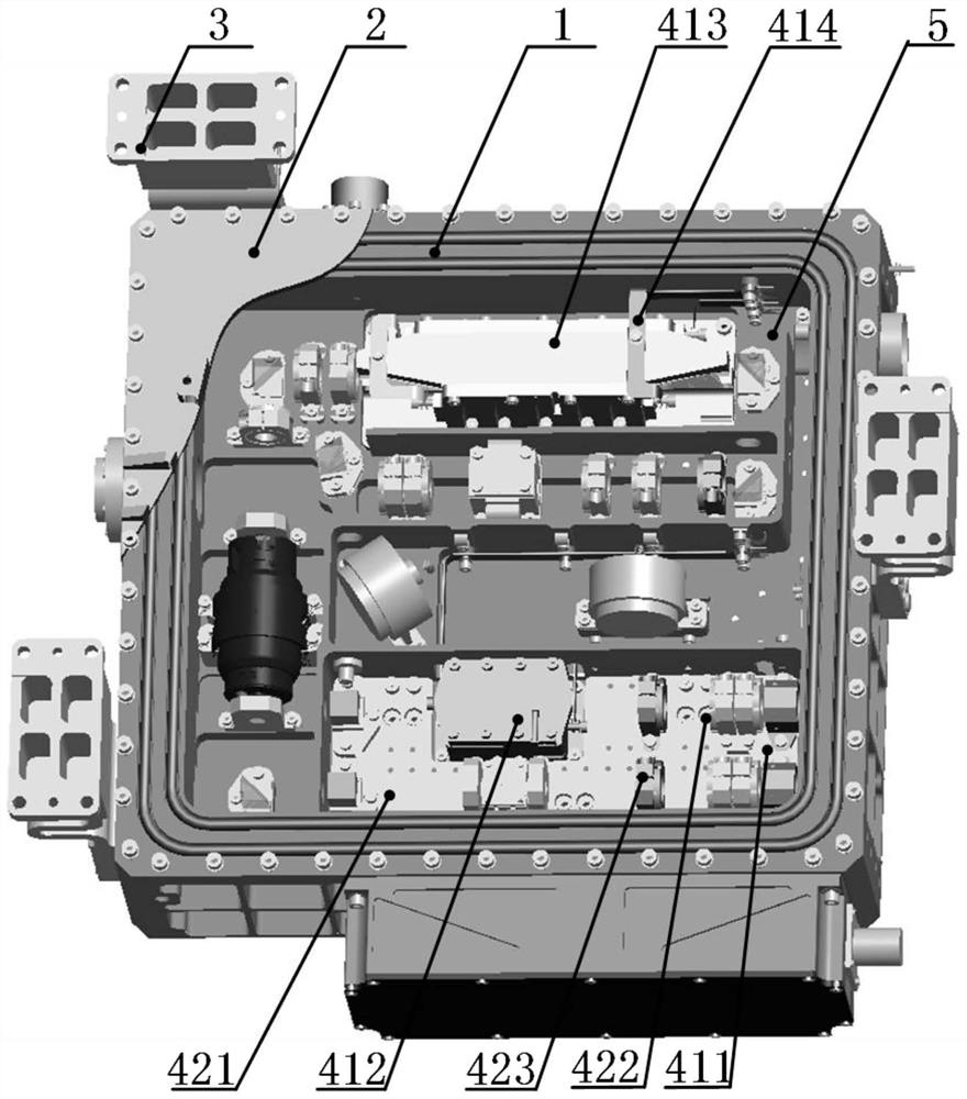
[0041] Such as figure 1 As shown, a space laser structure includes a laser housing 1, a cover plate 2 forming a sealing structure with the laser housing 1, and legs 3 arranged around the laser housing 1 for fixing the laser housing 1 and the satellite body and a laser assembly 4 disposed inside the laser housing 1;

[0042] The laser housing 1 and the cover plate 2 are sealed by an O-ring;

[0043] The laser housing 1 and the laser assembly 4 are provided with a protective layer 5, the protective layer 5 is clean air used to prolong the life of the laser assembly 4, and the pressure of the protective layer 5 is greater than 1 atmosphere;

[0044] The laser assembly 4 includes components 41 and an isolation assembly 42 for increasing mechanical stability. Some components 41 are directly fixed on the inner wall of the laser housing 1, and other components 41 are fixed to the laser housing 1 through the isolation assembly 42. .

Embodiment 2

[0046] Such as figure 1 As shown, a space laser structure includes a laser housing 1, a cover plate 2 forming a sealing structure with the laser housing 1, and legs 3 arranged around the laser housing 1 for fixing the laser housing 1 and the satellite body and a laser assembly 4 disposed inside the laser housing 1;

[0047] The laser housing 1 and the cover plate 2 are sealed by an O-ring, and the O-ring is a double O-ring;

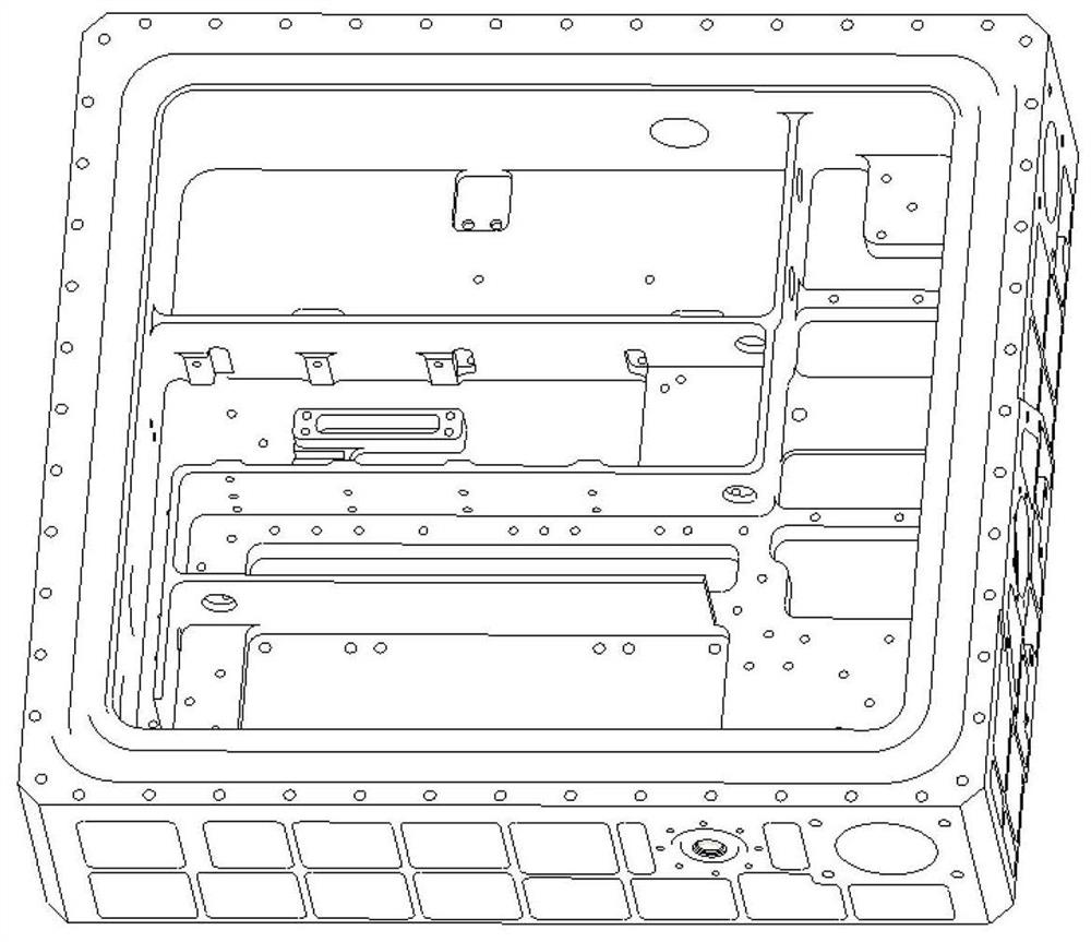
[0048] The laser housing 1 and cover plate 2 are made of aluminum 6061, such as figure 2 As shown, the side wall of the laser housing 1 is provided with lightening grooves;

[0049] The laser housing 1 and the laser assembly 4 are provided with a protective layer 5, the protective layer 5 is clean air used to prolong the life of the laser assembly 4, and the pressure of the protective layer 5 is greater than 1 atmosphere;

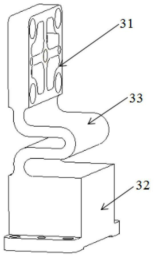
[0050] The material of leg 3 is TC17;

[0051] Such as image 3As shown, the leg 3 includes a first fixing seat 31 for fixing w...


PUM


Abstract

The invention provides a space laser structure. The space laser structure comprises a laser shell, a cover plate, supporting legs and a laser assembly, wherein the laser shell and the cover plate form a sealing structure; the supporting legs are arranged around the laser shell and are used for fixing the laser shell and a satellite main body; the laser shell and the cover plate are sealed through an O-shaped ring; and the laser shell and the laser assembly are provided with a protective layer, the laser assembly comprises components and an isolation assembly used for improving mechanical stability, part of the components are directly fixed on the inner wall of the laser shell, and the other part of the components are fixed with the laser shell through the isolation assembly. The space laser structure in a compact space is provided by theinvention,reduces the impact on the structural deformation of a resonant cavity from a space environment and the internal pollution of a laser housing through employing a high-strength and stable-performance material, the isolation of the resonant cavity, the power supply of a bus bar, and the double-O-ring sealing, and ensures the long service life and high reliability of the space laser.

Description

technical field [0001] The invention relates to the technical field of lasers, in particular to a space laser structure. Background technique [0002] Lidar is one of the important technical means to detect the types and spatial distribution of clouds and aerosols in the atmosphere, and is crucial for the study of climate change, environmental pollution and human health. Compared with ground-based lidar observations, spaceborne lidar can obtain the distribution of clouds and aerosols at different heights and types in a large area, which is useful for studying the microphysical characteristics of clouds and aerosols, radiative forcing effects, pollutant transmission, and analysis of pollution sources etc. have an irreplaceable role. As the emission light source of the laser radar system, the laser is a crucial single machine in the system. The laser pulse is emitted through the atmospheric laser, and the atmospheric detection channel detects the laser echo backscattered by t...

Claims


Application Information

Patent Timeline
Patent Type & Authority Applications(China)
IPC IPC(8): H01S3/02H01S3/08
CPCH01S3/02H01S3/08
Inventor 姜国庆赵一鸣李静魏祥通周永生
Owner BEIJING RES INST OF TELEMETRY
Why Eureka
Try Eureka