
Dustproof and moistureproof distribution box capable of continuously dissipating heat

A technology of power distribution box and cooling box, which is applied in substation/power distribution device casing, electrical components, substation/switch layout details, etc. It can solve the problems of heat loss, affecting the life of original components, affecting the use of equipment, etc., to prevent loss , save labor and realize the effect of automation

Inactive Publication Date: 2021-04-09
上海竭迷电子科技有限公司
View PDF0 Cites 1 Cited by
  • Summary
  • Abstract
  • Description
  • Claims
  • Application Information

AI Technical Summary

Problems solved by technology

[0002] The distribution box is a large number of parameters in the data, and generally constitutes a low-voltage distribution box. According to the electrical wiring, it is required to assemble switchgear, measuring instruments, protective appliances and auxiliary equipment in a closed or semi-closed metal cabinet or on a screen width to form a low-voltage distribution box. During normal operation, the circuit can be connected or disconnected by means of a manual or automatic switch. Because there are too many devices inside the distribution box, a certain amount of heat will be generated after long-term use, and the inside of the distribution box is closed, so that the heat cannot be lost. As a result, the life of the original components will be affected, and accidents such as fire may even occur when the temperature is too high. At this stage, most of the heat dissipation is carried out by blowing the fans to the inside. At this time, a large amount of dust will be brought into the inside of the distribution box. It will affect its use, and dust is easy to attract water vapor, which will cause moisture inside the distribution box, thereby affecting the use of equipment. In view of the above shortcomings, the present invention has improved

Method used


Image

  • Dustproof and moistureproof distribution box capable of continuously dissipating heat
  • Dustproof and moistureproof distribution box capable of continuously dissipating heat
  • Dustproof and moistureproof distribution box capable of continuously dissipating heat

Examples


Embodiment Construction

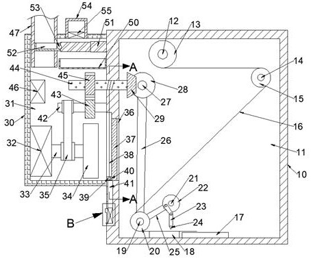
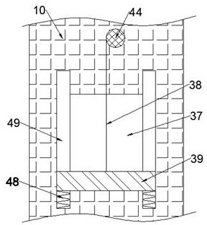
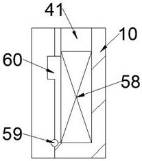
[0016] Combine below Figure 1-3 The present invention is described in detail, wherein, for the convenience of description, the orientations mentioned below are defined as follows: figure 1 The up, down, left, right, front and back directions of the projection relationship itself are the same.

[0017] A continuous heat dissipation dust-proof and moisture-proof distribution box described in conjunction with accompanying drawings 1-3 includes a distribution box 10 and a part chamber 11 arranged in the distribution box 10, and the part chamber 11 rotates on the rear wall An adhesive tape shaft 12 is provided, and an adhesive tape reel 13 is fixedly arranged on the adhesive tape reel 12, and an adhesive tape 16 is wound on the adhesive tape reel 13, and the adhesive tape 16 extends to the right and can drive the adhesive tape reel 13 rotates, and the bottom of the part chamber 11 is rotated to be provided with a transmission shaft 19, and the transmission shaft 19 is fixedly pro...


PUM


Abstract

The invention discloses a dustproof and moistureproof distribution box capable of continuously dissipating heat. The dustproof and moistureproof distribution box comprises a distribution box and a part cavity arranged in the distribution box; an adhesive tape shaft is rotatably arranged on the rear wall of the part cavity; an adhesive tape reel is fixedly arranged on the adhesive tape shaft. The dustproof and moistureproof distribution box of the invention is provided with a rotating fan which blows air to dissipate the heat of the distribution box, so that heat generated by internal components of the distribution box is continuously led to the outside, loss caused by heat generation of the equipment in the distribution box is prevented; meanwhile, the fan rotates to drive a cleaning brush to periodically move, dust on the surface of a dust blocking plate is periodically cleaned, the influence of dust blockage on heat dissipation is prevented; a dust bonding adhesive tape is arranged in the distribution box, so that dust floating in the distribution box can be bonded, the internal cleaning state of the distribution box is greatly improved; the automation of a treatment process is realized, the treatment efficiency is greatly improved, and the labor force is saved.

Description

technical field [0001] The invention relates to a dust-proof and moisture-proof distribution box for continuous heat dissipation, and mainly relates to the technical field of distribution boxes. Background technique [0002] The distribution box is a large number of parameters in the data. It generally constitutes a low-voltage distribution box. During normal operation, the circuit can be connected or disconnected by means of a manual or automatic switch. Because there are too many devices inside the distribution box, a certain amount of heat will be generated after long-term use, and the inside of the distribution box is closed, so that the heat cannot be lost. As a result, the life of the original components will be affected. When the temperature is too high, accidents such as fires may even occur. At this stage, fans are mostly used to blow the heat to the inside for heat dissipation. At this time, a large amount of dust will be brought into the distribution box. It will...

Claims


Application Information

Patent Timeline
Patent Type & Authority Applications(China)
IPC IPC(8): H02B1/56H02B1/28H02B1/46
CPCH02B1/28H02B1/46H02B1/565
Inventor 尹利
Owner 上海竭迷电子科技有限公司
Learn More