

Floor scrubber
The technology of a washing machine and a main unit is applied in the field of household cleaning products, which can solve the problems of forgetting to use, consuming a lot of time and resources, blocking the sewer pipes, etc., and achieves the effects of prolonging the service life, simple structure and ensuring safe use.
- Summary
- Abstract
- Description
- Claims
- Application Information
AI Technical Summary
Problems solved by technology
Method used
Image

Examples
Embodiment Construction
[0035] The technical solutions of the various embodiments of the present invention will be clearly and completely described below in conjunction with the accompanying drawings. Apparently, the described embodiments are only some of the embodiments of the utility model, not all of them. All other embodiments obtained by persons of ordinary skill in the art based on the embodiments of the present utility model without creative efforts belong to the protection scope of the present invention.
[0036] The present invention will be described in further detail below through specific embodiments and in conjunction with the accompanying drawings.
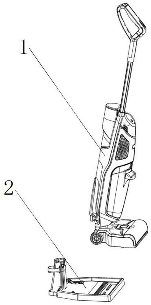
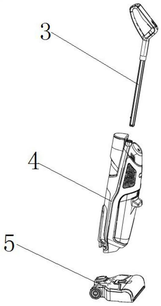
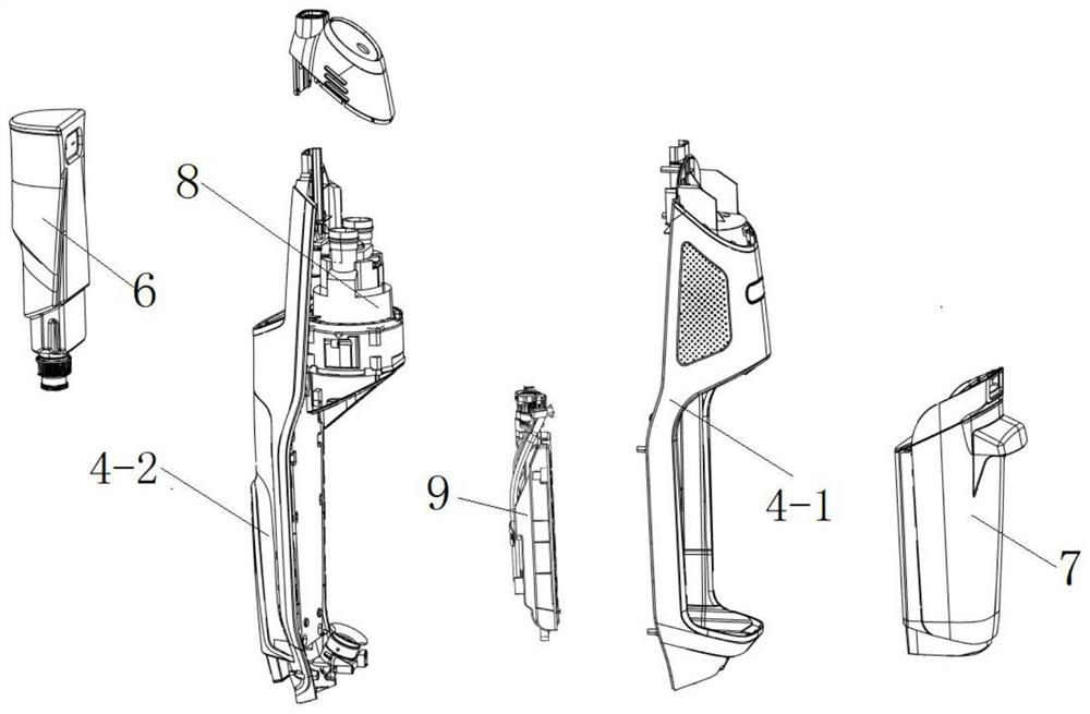
[0037] A scrubber, comprising a scrubber body 1 and a charging base 2, the scrubber body 1 includes a handle assembly 3, a host assembly 4, and a cleaning head assembly 5, and the handle assembly 3 is connected above the host assembly 4 , the cleaning head assembly 5 is connected below the host assembly 4, the host assembly 4 includes a cle...
PUM
 Abstract
Description
Claims
Application Information