Wheel set shaft diameter self-adaptive lifting and centering device and centering method thereof

A centering device and wheel-to-shaft technology, applied in the field of CNC lathes, can solve the problems of time-consuming and labor-intensive clamping process, poor accuracy and repeatability, and many manpower, and achieve the effect of simple operation without manual intervention

Pending Publication Date: 2021-04-13
江西奈尔斯西蒙斯赫根赛特中机有限公司
View PDF0 Cites 0 Cited by
  • Summary
  • Abstract
  • Description
  • Claims
  • Application Information

AI Technical Summary

Problems solved by technology

[0004] (1) There is no automatic measurement function, and it cannot adapt to the lifting and centering of wheelsets with different wheel diameters. Manual adjustment must be used to lift the wheelset to the centering top position
(2) Due to the different degrees of wear on the left and right rims of the wheel set, the wheel diameters are different. When the wheel rim is used to lift, the center holes of the left and right shaft ends of the wheel set are not on the same horizontal line, which increases the difficulty of manual alignment.
(3) The lifting and centering efficiency of the wheel set is low, and the accuracy and repeatability are poor. The process of lifting and centering the wheel set is time-consuming and labor-intensive. The whole process requires a lot of manpower and requires high operating requirements for the operator.

Method used


Image

  • Wheel set shaft diameter self-adaptive lifting and centering device and centering method thereof
  • Wheel set shaft diameter self-adaptive lifting and centering device and centering method thereof

Examples


Embodiment Construction

[0037] The technical solutions in the device embodiments of the present invention will be clearly and completely described below in conjunction with the accompanying drawings in the device embodiments of the present invention. Obviously, the described embodiments are only part of the embodiments of the device, not all of them. All other embodiments obtained by persons of ordinary skill in the art without making creative efforts belong to the protection scope of the device of the present invention.

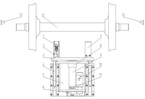
[0038] Such as figure 1 As shown, the present invention discloses a self-adaptive lifting and centering device for the shaft diameter of a wheel set, which includes a lifting bracket 3 and a pair of V-shaped brackets 7 arranged axially symmetrically above the lifting bracket 3; 3 A pair of guide rods 4 on both sides of the bottom; also includes a probe rod 1 installed in the center of the V-shaped bracket 7, and a pull-wire encoder 2 installed under the V-shaped bracket 7; V-shaped...


PUM


Abstract

The invention discloses a wheel set shaft diameter self-adaptive lifting and centering device. The device comprises a lifting bracket (3), a pair of V-shaped brackets (7) arranged above the lifting bracket (3) in an axial symmetry mode, a pair of guide rods (4) arranged on two sides below the lifting bracket (3) in an axial symmetry manner, a feeler lever (1) installed in the centers of the V-shaped brackets (7), and a stay wire encoder (2) installed below the V-shaped brackets (7), and the V-shaped brackets (7) are fixedly connected with the guide rods (4). The invention further discloses the centering method for the wheel set shaft diameter self-adaptive lifting and centering device. The centering method comprises seven automatic steps. Wheel sets are lifted in a wheel shaft lifting mode, it is guaranteed that center holes in the left shaft ends and the right shaft ends of the wheel sets are located on the same horizontal line, centering of tips at the two ends is greatly facilitated, the wheel sets with different shaft diameters are conveniently and rapidly lifted to the centering position, and compared with the prior art, the device has the advantages that operation is easy, efficiency is high, and accuracy is good.

Description

technical field [0001] The invention relates to the technical field of numerically controlled lathes, and discloses a wheel-set shaft-diameter self-adaptive lifting centering device and a centering method thereof. Background technique [0002] At present, the wheel set tread repairing processing equipment of domestic rail transit vehicles is mainly based on CNC wheel lathes. In the process of repairing and processing the wheel set treads of rail transit vehicles by CNC wheel lathes, it is necessary to lift the wheels of the propulsion equipment along the track. Clamp to the top-centered top-tight position. [0003] Existing numerically controlled wheel lathes use the mode of lifting and supporting the rim of the wheel set to lift the wheel set to the top-centered top position. The existing lifting and centering methods mainly have the following deficiencies: [0004] (1) There is no automatic measurement function, and it cannot adapt to the lifting and centering of wheelse...

Claims


Application Information

Patent Timeline
Patent Type & Authority Applications(China)
IPC IPC(8): B23B25/06B23Q1/72B23Q15/22
CPCB23B25/06B23Q1/72B23Q15/22
Inventor 杨建峰周海泉朱德生付道林金明亮姜曦
Owner 江西奈尔斯西蒙斯赫根赛特中机有限公司
Why Eureka
Try Eureka