Supercharge Your Innovation With Domain-Expert AI Agents!

Device and method for rapid cooling of high temperature gas

A high-temperature gas, rapid cooling technology, applied in the field of rapid cooling devices and processes, to overcome the problem of limited application, safe and reliable cooling, and reduce the risk of cooling blockage

Active Publication Date: 2022-02-18
WANHUA CHEM GRP CO LTD +1
View PDF7 Cites 0 Cited by
  • Summary
  • Abstract
  • Description
  • Claims
  • Application Information

AI Technical Summary

Problems solved by technology

This method can overcome heat exchanger blockage, replace filters and coolers, effectively reduce the risk of solid gas cooling blockage, make the cooling of corrosive gas safer and more reliable, enable the device to run for a long period, and overcome the application of special materials. It can be widely used in the fields of HCl oxidation, cracking gas and waste gas treatment of incineration systems

Method used


Image

  • Device and method for rapid cooling of high temperature gas
  • Device and method for rapid cooling of high temperature gas
  • Device and method for rapid cooling of high temperature gas

Examples


Embodiment 1

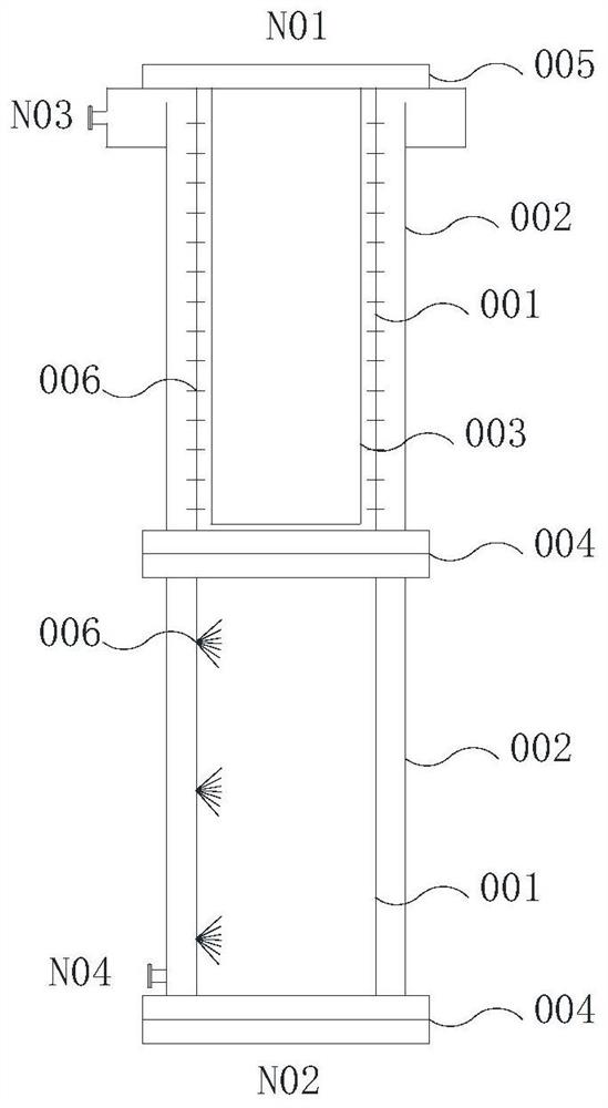
[0036] use as figure 2 The quenching device shown is composed of two sections a+b. The cylindrical casing of the quenching device has a diameter of 400 mm and is divided into two sections, the first section is 1.0 m in height, and the second section is 1.0 m in height. The distance between the cylindrical shell and the jacket of each section is 30mm, the first section has an inner cylinder, the second section has no inner cylinder, and the distance between the first cylindrical shell and the inner cylinder is 5mm , the cylindrical shell of the quenching device is made of tantalum material, the inner side of the jacket outside the shell is CS lined with tantalum, the inner cylinder is made of tantalum material, the nozzle material is made of tantalum material, the thickness of the cylindrical shell is 4mm, and the jacket outside the shell The thickness is 20mm, the thickness of the inner cylinder is 3mm, and the thickness of the lining material inside the jacket is 1.2mm.

...

Embodiment 2

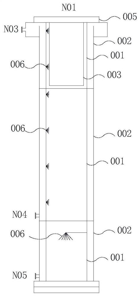
[0041] use as image 3 The quenching device shown is composed of sections a+b+b. The cylindrical shell of the quenching device has a diameter of 2000mm and is divided into three sections. The height of the first section is 0.5m, the height of the second section is 1m, and the height of the third section is 0.5m. The connection method of each section is welding. The distance between each cylindrical shell and the jacket is 50mm, the first section has an inner cylinder, the second and third sections have no inner cylinder, the distance between the cylindrical shell and the inner cylinder is 5mm, and the quenching device The cylindrical shell is 304, the inner side of the jacket outside the shell is 304, the material of the nozzle is 304, the material of the inner cylinder is 304, the thickness of the cylindrical shell is 5mm, the thickness of the jacket outside the shell is 15mm, and the inner cylinder The thickness is 1.5mm.

[0042]The inner member of the cylindrical shell o...


PUM

PropertyMeasurementUnit
diameteraaaaaaaaaa
heightaaaaaaaaaa
thicknessaaaaaaaaaa

Abstract

The invention relates to a device and method for rapid cooling of high-temperature gas, comprising one or more cylindrical shells connected to each other, a jacket on the outside of the shell, an inner cylinder at least inside the first shell, and sealing the first circular shell. The heat insulation gasket on the top of the inner cylinder in the cylindrical shell and the first cylindrical shell is distributed along the wall of the shell, and communicates with the inner cavity of the jacket and the interior of the shell for distributing the liquid in the jacket to the shell. Components, the high-temperature gas inlet located on the heat insulating gasket, the gas-liquid two-phase outlet located at the bottom of the shell or the bottom of the last shell, and the cooling liquid inlet and outlet connected to the inside of the jacket. This method can replace filters and coolers, effectively reduce the risk of solid gas cooling blockage, make the cooling of corrosive gas safer and more reliable, enable the device to run for a long period, and improve the application range of special materials, which can be widely used In the field of HCl oxidation, cracking gas and waste gas treatment of incineration system.

Description

technical field [0001] The invention relates to a device and method for rapid cooling of high-temperature gas, which can be applied to solid-containing and highly corrosive gases, belongs to the application field of chemical equipment, and particularly relates to a rapid cooling device and process, which can be widely used in HCl oxidation, Cracking gas and incineration system exhaust gas treatment field. Background technique [0002] In the isocyanate process, chlorine balance is an important indicator that affects product cost. Currently, the most commonly used methods for dealing with HCl are: 1) direct absorption with lye, resulting in a large waste of chlorine resources; 3) The Deacon catalytic oxidation method directly oxidizes HCl into chlorine, which can realize the recycling of chlorine. CN101511728B describes this method. Through the process and equipment analysis in this patent, the high temperature reaction gas contains HCl, Cl 2 , O 2 and water, nickel and t...

Claims


Application Information

Patent Timeline
Patent Type & Authority Patents(China)
IPC IPC(8): F23G5/44F23G5/46F23J15/06
CPCF23G5/44F23G5/46F23J15/06F28C3/06F23J2219/80B01D49/00C01B7/0743C01B2210/0025C01B2210/0057C01B2210/0062
Inventor 宋明焱陈毅峰乔小飞柯长颢王京奎贾海兵赵楠姜进科刘鹏于天勇宋艳杨在刚罗务习徐长宝刘俊贤国建茂
Owner WANHUA CHEM GRP CO LTD
Features
  • R&D
  • Intellectual Property
  • Life Sciences
  • Materials
  • Tech Scout
  • Unparalleled Data Quality
  • Higher Quality Content
  • 60% Fewer Hallucinations
Learn More