
Medical infrared thermal imaging detection robot and treatment method

A technology of infrared thermal imaging and treatment method, applied in the field of medical devices, can solve the problems of the lifting control handle being unable to move horizontally, ignoring the rigor of medical examination, and poor clinical guidance, and achieving improved speed, improved intelligence, and wide shooting field of vision. clear effect

Pending Publication Date: 2021-04-16
BEIJING JISHUITAN HOSPITAL
View PDF0 Cites 0 Cited by
  • Summary
  • Abstract
  • Description
  • Claims
  • Application Information

AI Technical Summary

Problems solved by technology

Disadvantages: 1. The lifting control handle cannot move horizontally, which limits the shooting field of view
2. Patients operate independently, while protecting privacy but ignoring the rigor of medical examination, the collected images are inconsistent, and the clinical guidance significance is poor

Method used


Image

  • Medical infrared thermal imaging detection robot and treatment method
  • Medical infrared thermal imaging detection robot and treatment method
  • Medical infrared thermal imaging detection robot and treatment method

Examples


Embodiment 1

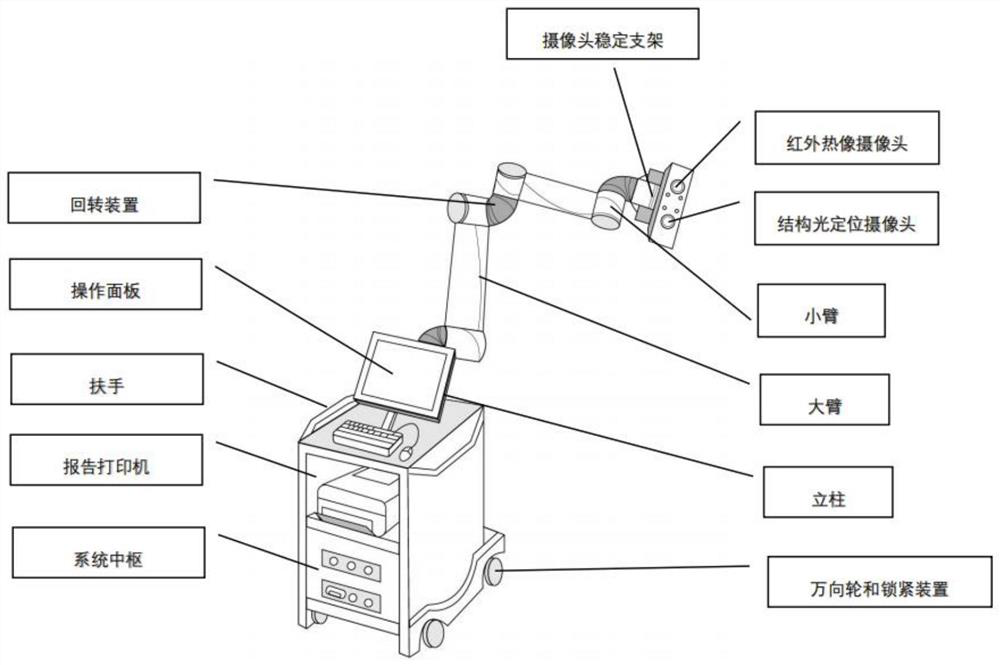
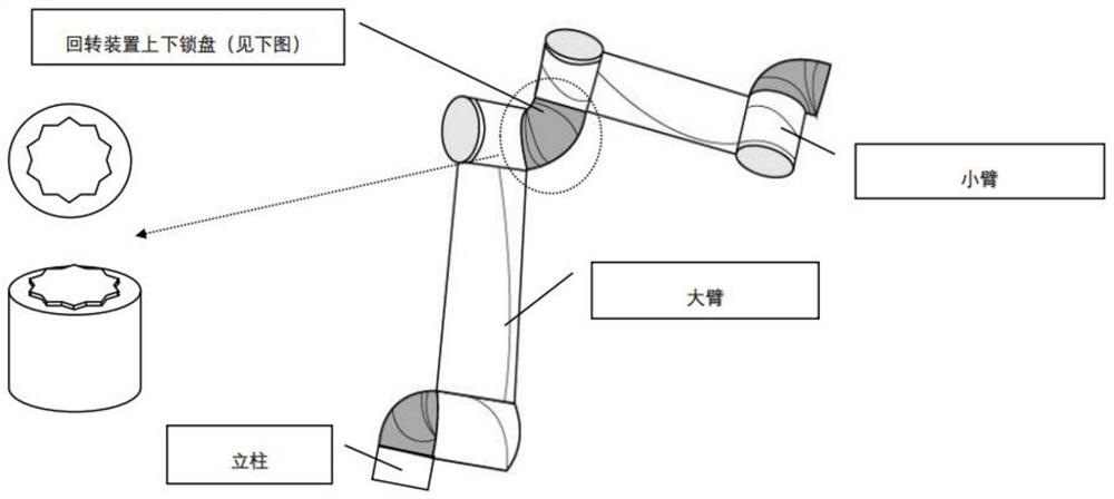
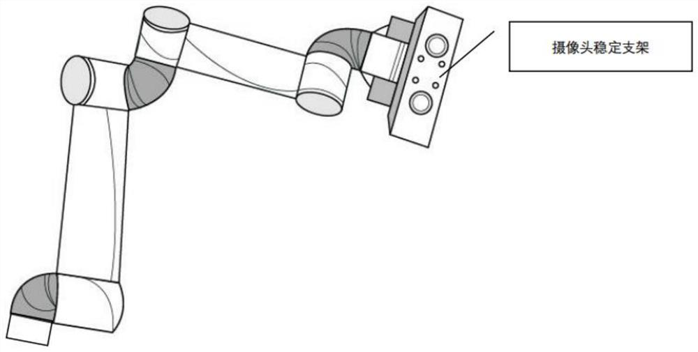
[0048] refer to Figure 1-3 , a medical infrared thermal image detection robot, comprising an infrared thermal imager, a structured light locator, a mechanical arm and an operating table; The racks are fixed side by side at the end of the robotic arm.

[0049] In this embodiment, the mechanical arm is composed of joints with multiple degrees of freedom, and can move automatically / manually in all directions. The manual movement pedal is installed below the main machine, and the mechanical arm is installed above the main machine.

[0050] In this embodiment, the mechanical arm includes a column, a slewing device, a large arm, a small arm and a camera stabilization bracket; the column is installed on the console, and the column is a hollow thin-walled short metal tube with a main bearing and a The cable passes through, and the column is connected to one end of the slewing device. The slewing device is made of metal alloy, which is light and durable. The long tube structure is t...

Embodiment 2

[0057] Such as Figure 4 Shown, disclose a kind of treatment method based on above-mentioned embodiment, comprise the steps:

[0058] (1) Register the patient's basic information and diseased parts in the information storage system;

[0059] (2) Drive the robotic arm to reach the designated shooting location;

[0060] (3) Infrared thermal imaging camera takes images to obtain a diagnosis report;

[0061] (4) Print the report, upload the report to the cloud, and copy the image for review.

[0062] In this embodiment, the step (2) is specifically:

[0063] Automatic: The structured light positioning system is taken by the structured light locator located at the end of the robotic arm to obtain patient images, which are transmitted to the main machine by cable. Through the structured light positioning system in the main machine, the three-dimensional image of the patient is simulated, and the disease is identified through the information storage system. The path planning is f...


PUM


Abstract

The invention discloses a medical infrared thermal image detection robot and a treatment method. The medical infrared thermal imaging detection robot comprises an infrared thermal imager, a structured light positioning instrument, a mechanical arm and an operation table, the mechanical arm is of a joint type multi-degree-of-freedom structure, the thermal infrared imager and the structured light positioning instrument are arranged at the tail end of the mechanical arm, and the mechanical arm is arranged on the operation table. On the premise that the existing diagnosis precision is not influenced, the intelligence of instruments and equipment is improved, the shooting visual field is wider and clearer, and the positioning is more accurate. Therefore, the medical infrared thermal image detection robot is beneficial to the popularization of the development of medical infrared thermal imaging technology, the instrument operation is more convenient, the shooting data is more scientific and rigorous, and the public recognition degree is improved.

Description

technical field [0001] The invention relates to the technical field of medical devices, in particular to a medical infrared thermal image detection robot and a treatment method. Background technique [0002] The infrared thermal imaging camera can convert the infrared radiation energy emitted by the organism through a special scanning system and a specific detector to complete the photoelectric conversion. The converted electrical signal can be converted into an image signal after system processing, and formed on the display. Intuitive thermal image map. The color distribution of the thermal image corresponds to the temperature, and the color and temperature scale on the display can be read intuitively. Usually warm colors are labeled as high temperature and cool colors represent low temperature. If human organs and tissues in the body become diseased, it will lead to abnormal local temperature. According to the current research, the temperature will increase for inflamma...

Claims


Application Information

Patent Timeline
Patent Type & Authority Applications(China)
IPC IPC(8): A61B5/00A61B5/01B25J11/00B25J18/00G06T7/00G06T7/13G06T17/00
Inventor 刘亚军郭安忆刘佳佳
Owner BEIJING JISHUITAN HOSPITAL
Learn More