Automatic liquid transfer device

A pipetting and automatic technology, applied in the direction of measuring tube/pipette, etc., to achieve the effect of multi-depth liquid transfer

Pending Publication Date: 2021-04-16
BEIJING UNIV OF CHEM TECH
View PDF18 Cites 1 Cited by
  • Summary
  • Abstract
  • Description
  • Claims
  • Application Information

AI Technical Summary

Problems solved by technology

[0004] The purpose of the present invention is in order to overcome the defective of prior art, in order to solve the pro

Method used


Image

  • Automatic liquid transfer device
  • Automatic liquid transfer device
  • Automatic liquid transfer device

Examples


Example Embodiment

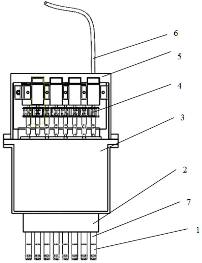
[0033] An automatic liquid pipetting device, such as figure 1 As shown, it includes the following parts: pipette gun shell, pipette gun top cover, pipette gun inner tube, first sliding table guide rail, second sliding table guide rail, motor, thin tube, syringe, tip loading and unloading shell.

[0034] Among them, the number of inner tubes of the pipette is increased or decreased according to actual needs, figure 1 Taking 8 pipettes as an example, any number of 1-8 channels can be pipetted at multiple depths according to the needs. The inner sleeve covered by the inner tube of the pipette gun and the outer sleeve installed on the tip loading and unloading shell form a parallel slide for the inner tube to move up and down. The inner tube of the pipette can move in the channel with low friction and no deviation, which is used for the removal of disposable pipette tips.

[0035] Among them, the relative position of the inner tube of the pipette is determined by the internal s...


PUM

PropertyMeasurementUnit
Widthaaaaaaaaaa

Abstract

The invention belongs to the technical field of liquid transfer, and relates to an automatic liquid transfer device, which mainly solves the problem of miniaturization of a motor-driven liquid transfer device. The automatic liquid transfer device is characterized in that a motor driving mechanism and a liquid transfer gun inner tube jointly form a liquid transfer gun tube module, the module can realize the independent control of a liquid transfer gun tube and the synchronous control of a plurality of gun tubes, and in addition, the operation of assembling and disassembling a gun head can be independently finished. The module is connected with an injector through a slim tube, and during liquid transfer operation, the injector does not need to be moved, and only the liquid transfer gun tube module needs to be controlled to move through the Z axis of the XYZ three-axis platform or a mechanical arm. The problem that a liquid transfer gun barrel in a small multi-channel liquid transfer device cannot be independently controlled can be solved, and the device has important significance in application of the multi-channel liquid transfer device in a complex and narrow environment.

Description

technical field [0001] The invention belongs to the technical field of liquid transfer, and relates to an automatic liquid transfer device. Background technique [0002] Automatic pipetting devices are widely used in biochemical research laboratories, hospitals, and pharmaceutical companies, and generally include pipetting sleeves, piston rods, and pipette tips. When drawing liquid, as the piston rod in the pipetting sleeve is pulled out, the liquid is sucked into the disposable tip under the action of negative pressure in the pipetting sleeve; in the same way, the piston rod is pushed, and the closed space inside the pipette gun Reduced, according to the principle of air displacement, the same volume of liquid in the disposable tip will also be transferred to the test tube. [0003] The traditional multi-channel pipetting device has a large drive device and can only perform pipetting operations in a designated space; some small multi-channel pipetting devices often use pne...

Claims


Application Information

Patent Timeline
IPC IPC(8): B01L3/02
Inventor 陈国华高圆张爱军
Owner BEIJING UNIV OF CHEM TECH
Why Eureka
Try Eureka