Full-automatic sand core dip-coating system and dip-coating method thereof

A fully automatic, sand core technology, applied in casting and molding equipment, metal processing equipment, manufacturing tools, etc., to achieve uniform Baume degree, improve quality, and reduce cracks.

Pending Publication Date: 2021-04-16
苏州艾励德智能装备有限公司
View PDF0 Cites 4 Cited by
  • Summary
  • Abstract
  • Description
  • Claims
  • Application Information

AI Technical Summary

Problems solved by technology

The existing technology can only solve the coating cycle feeding of the dip coating tank, and cannot realize the uninterrupted clamping, purging, dip coating and other processes with high quality. The technical problem to be solved is to realize the complete process flow of full automation At the same time, ensure the quality of dip coating on the surface of the product, thereby improving the surface quality of casting products and improving production efficiency

Method used


Image

  • Full-automatic sand core dip-coating system and dip-coating method thereof
  • Full-automatic sand core dip-coating system and dip-coating method thereof
  • Full-automatic sand core dip-coating system and dip-coating method thereof

Examples


Embodiment 1

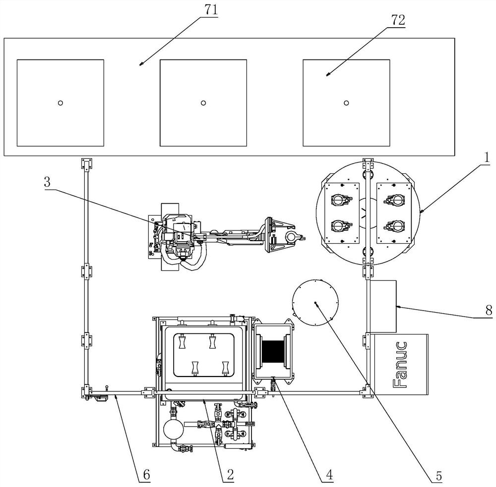
[0046] The fully automatic sand core dip coating system is started by the control system 8. The fully automatic sand core dip coating system includes a feeding unit 1, a dip coating unit 2, a clamping unit 3, a cleaning unit 4, a purging unit 5 and electrical connections with each unit. Sexually connected control system8.

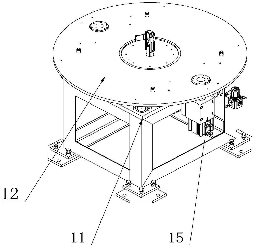
[0047] First, the sand core 9 blank is provided by the feeding unit 1, and the operator places the sand core 9 on the double-station rotary table outside the safety fence 626. The feeding unit 1 includes a base 11, a double-station turntable 12, and a first driving mechanism. 13. The supporting bearing 14 and the positioning mechanism 15, the double-station turntable 12 is installed on the top of the base 11 and its top surface has several sand core 9 molds 121 for placing the sand core 9, and the top surface of the sand core 9 mold 121 has Positioning block 122, a support bearing 14 is provided at the bottom of the double-station turntable and is rotatably...

Embodiment 2

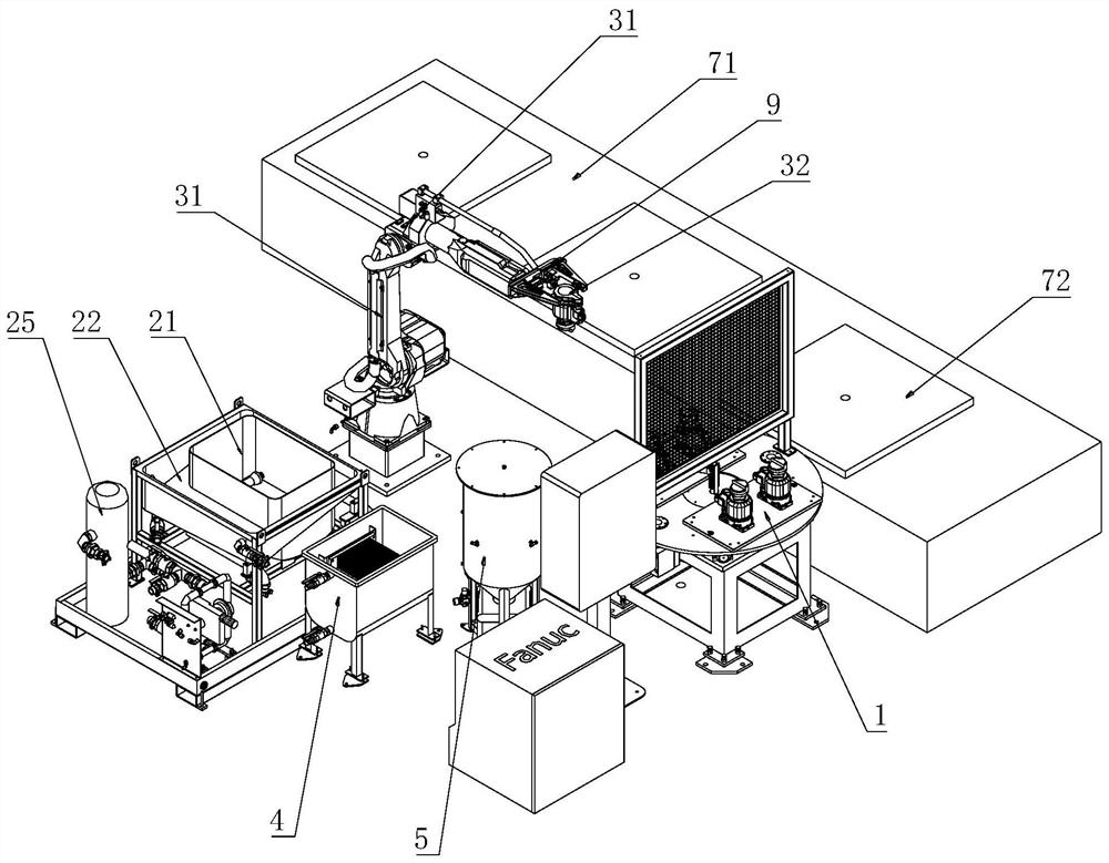
[0052] Embodiment 2: The difference from Embodiment 1 is that in order to facilitate the clamping of sand cores 9 of different specifications, the fixture 32 and the robot 31 can be detachably connected, and can be connected by screws, clamping and locking. The robot 31 includes a robot Main body 311, base 312 and electric control system 313, robot main body 311 is installed on the base 312, and its connection of the two can be motor, gear drive its rotation, electric control system 313 and robot main body 311 and control system 8 are electrically balanced. connect.

Embodiment 3

[0053] Embodiment 3: Different from Embodiment 1, the present invention also includes a safety fence 626 for overall mechanical external protection and a transfer roller assembly 71 for circulating the sand core 9 after spin coating, on one side of the double-station turntable 12 Located in the safety fence and the other side outside the safety fence, the transfer roller assembly 71 is arranged on one side of the robot 31, in detail, the safety fence 626 includes a column 61, a fence 62, a safety door 63 and a door lock 64, and the column 61 is provided with Several, the fence 62 is provided with several leaves and is installed on the column 61, and each fence 62 encloses the whole mechanical device in the system frame, and one of the fences 62 is provided with a safety door 63, and a door lock 64 is installed on the safety door 63, and the door lock 64 is connected with the control system 8, once the safety door 63 is opened, the machine.

[0054] A fully automatic sand core ...


PUM


Abstract

The invention discloses a full-automatic sand core dip-coating system and a dip-coating method thereof. The full-automatic sand core dip-coating system comprises a feeding unit, a dip-coating unit, a clamping unit, a cleaning unit and a control system electrically connected with all the units. The feeding unit is used for providing a sand core blank; the clamping unit is used for clamping and transferring a sand core, and the dip-coating unit is used for dip-coating the sand core, and comprises a dip-coating module and a circulating module; and a cleaning device is used for cleaning a fixture. According to the dip-coating system, the integrated automatic process of sand core feeding, purging, dip-coating, conveying and fixture cleaning is achieved, not only is the labor cost greatly saved, but also the production efficiency and the casting quality are improved.

Description

technical field [0001] The invention relates to the technical field of sand core dip coating, in particular to an automatic sand core dip coating system and a dip coating method thereof. Background technique [0002] The supporting hydraulic valves and hydraulic pumps in the construction machinery industry generally adopt the sand core casting process in the production and casting process. Generally used sand cores (inner cores) need to be dip-coated and dried before use. In the dip coating process of the sand core, the traditional method is to manually take the sand core and dip it into the paint, then manually shake off the excess paint on the surface of the sand core, and then put it on the roller tray in the front section of the drying furnace for surface coating. drying. This production process adopts the methods of manual dip coating, manual spin coating, and manual handling and discharging. The labor intensity of personnel is high and boring, and the production effic...

Claims


Application Information

Patent Timeline
Patent Type & Authority Applications(China)
IPC IPC(8): B22C23/02
Inventor 马艳东刘江来
Owner 苏州艾励德智能装备有限公司
Why Eureka
Try Eureka