Numerical control grinding machine for engine crankshaft

A CNC grinding machine and engine technology, applied in the direction of grinding machines, parts of grinding machine tools, and machine tools designed for grinding the rotating surface of workpieces, etc., can solve the problems of different grinding time, crankshaft machining accuracy, surface roughness and waviness of the machined surface Quality impact, different grinding force and other issues, to achieve the effect of improving machining accuracy

Pending Publication Date: 2021-04-16
YANGZHOU UNIV
View PDF11 Cites 0 Cited by
  • Summary
  • Abstract
  • Description
  • Claims
  • Application Information

AI Technical Summary

Problems solved by technology

However, when the crankshaft rotates at a constant speed, there will be some problems in the grinding process: the actual grinding depth at each tangent point (grinding point) of the connecting pin is different
Therefore, the grinding time of the grinding wheel at each tangent point (grinding point) on the connecting rod journal is different; the relative grinding speed at each tangent point (grinding point) on the connecting rod neck is different; , the magnitude and direction of the speed at the grinding point are different, so the grinding force is also different; quality will have some effect

Method used


Image

  • Numerical control grinding machine for engine crankshaft
  • Numerical control grinding machine for engine crankshaft
  • Numerical control grinding machine for engine crankshaft

Examples


Embodiment Construction

[0046] Embodiments of the present invention will be described below with reference to the drawings.

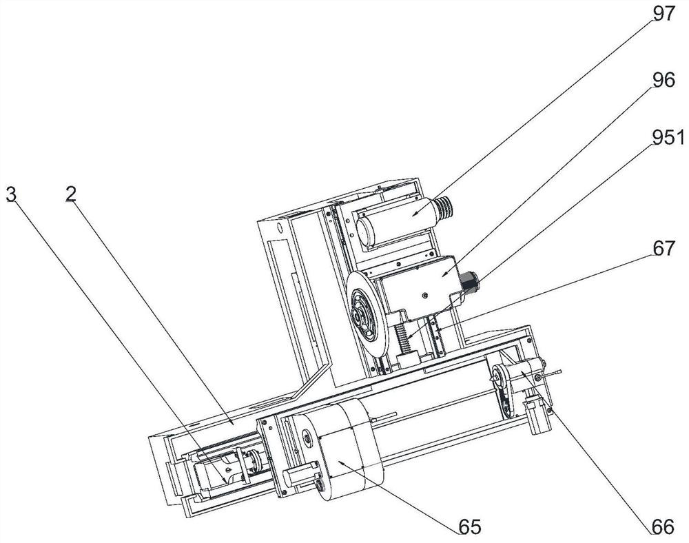
[0047] The present invention is made up of five parts, comprises bed base 2, longitudinal feeding system assembly 3, headstock assembly 65, tailstock assembly 66 and grinding wheel frame assembly 1. as attached figure 1 As shown: the bed base 2 is provided with a longitudinal feed system 3 and a backing plate 92 . The bed base 2 is connected to the longitudinal feed system 3 through the longitudinal ball screw 47, the wheel frame assembly 1 is connected to the backing plate 92 (arranged with the lateral feed system assembly), and the head frame assembly is connected to the guide rail of the upper workbench. Become 65, tailstock assembly 66.

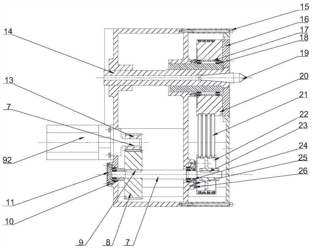
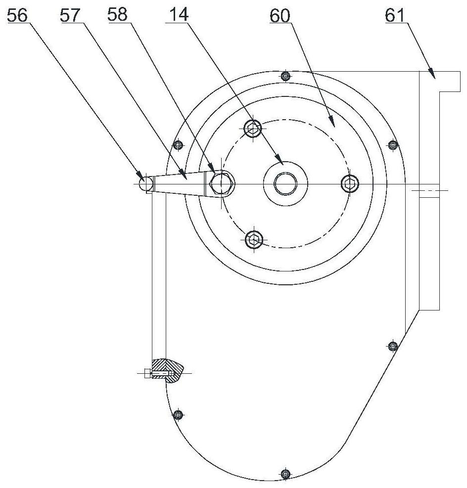
[0048] See figure 2 , image 3 : the AC servo motor 92 is fixed on the head frame box body 61 through bolts, the head frame driving rod 56 and the driving rod cover 57 are perpendicular to each other, the driving rod cover 57 is conn...


PUM


Abstract

The invention relates to a numerical control grinding machine for an engine crankshaft, and belongs to the technical field of grinding machines. The numerical control grinding machine is characterized by comprising a machine tool body base, a headstock assembly, a tailstock assembly and a grinding carriage assembly; a longitudinal feeding system assembly and a base plate are arranged on the machine tool body base, and a transverse feeding system assembly is arranged on the base plate; the headstock assembly and the tailstock assembly are oppositely arranged and installed on a workbench connected with the longitudinal feeding system assembly, and the grinding carriage assembly is installed on the base plate through the transverse feeding system assembly; and the headstock assembly and the tailstock assembly jointly clamp and fix the crankshaft, the crankshaft is driven through the headstock assembly, longitudinal displacement of the headstock assembly and the tailstock assembly is adjusted through the longitudinal feeding system assembly, transverse displacement of the grinding carriage assembly is adjusted through the transverse feeding system assembly, and therefore the crankshaft can be ground conveniently. According to the numerical control grinding machine, by controlling a controllable motor, the crankshaft can rotate at a variable speed in the grinding process, and it can be guaranteed that the crankshaft is at a constant speed at a grinding point in the grinding process.

Description

technical field [0001] The invention relates to a numerical control grinding machine for an engine crankshaft, belonging to the technical field of grinding machines. Background technique [0002] The crankshaft is one of the key parts of the engine. The parts have complex structures, large production batches and high precision requirements. The final processing of crankshafts still generally adopts grinding technology. In order to meet the increasing processing requirements of crankshafts, high requirements are put forward for crankshaft grinding machines. When the crankshaft rotates, by controlling the lateral feed speed of the grinding wheel so that it is always tangent to the connecting pin journal, the crankshaft rotates one revolution, thereby realizing the grinding of the connecting pin journal. However, under the condition that the crankshaft rotates at a constant speed, some problems will occur in the grinding process: the actual grinding depth at each tangent point...

Claims


Application Information

Patent Timeline
Patent Type & Authority Applications(China)
IPC IPC(8): B24B5/42B24B5/35B24B47/20B24B53/14
Inventor 宗轶琦张乾坤沈辉李红陶海
Owner YANGZHOU UNIV
Why Eureka
Try Eureka