

Vulcanization mold
A technology of vulcanizing molds and bottom fixing, applied in the field of molds, can solve the problems of inconvenient handling, excessive mold weight, etc., and achieve the effects of convenient transportation, improved machine service life, and power saving.
- Summary
- Abstract
- Description
- Claims
- Application Information
AI Technical Summary
Problems solved by technology
Method used
Image

Examples
Embodiment 1
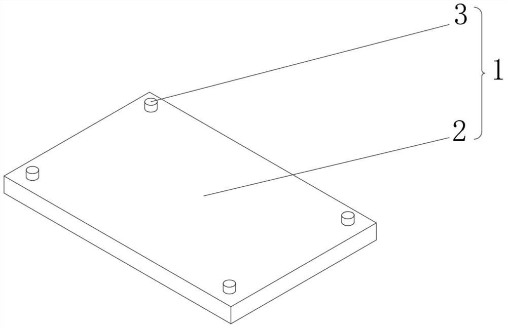
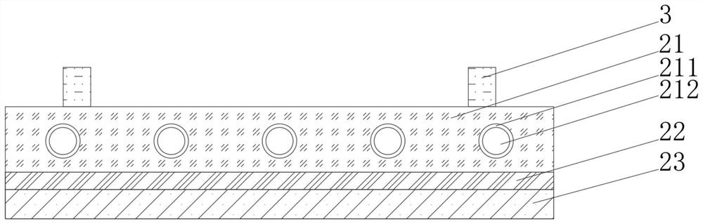
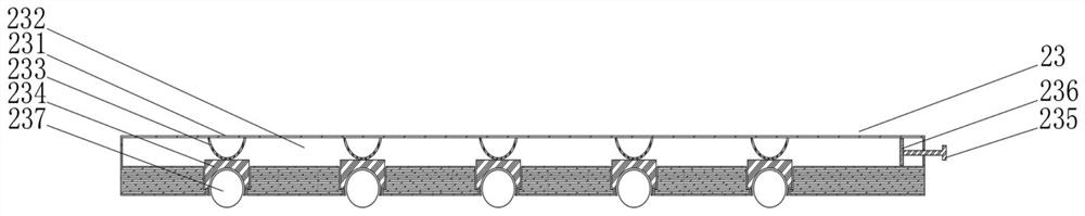
[0040] see Figure 1-3 , the present invention provides a technical solution: a vulcanization mold, including a vulcanization mold body 1 composed of a base 2 and a pad 3, the base 2 includes a heating plate 21, and a heating cavity 211 is opened inside the heating plate 21, and the heating cavity The inside of 211 is provided with a heating pipe 212, the top of the heating plate 21 is fixedly connected with the bottom of the block 3, the bottom of the heating plate 21 is fixedly connected with a heat insulating block 22, and the bottom of the heat insulating block 22 is fixedly connected with a sliding mechanism 23, sliding Mechanism 23 comprises receiving block 231, and accepting block 231 is provided with hydraulic cavity 232 inside, and the inner wall top of hydraulic cavity 232 is fixedly connected with elastic snap ring 233, and the bottom of elastic snap ring 233 is fixedly connected with push-out block 234, and accepting block 231 A piston rod 235 is threadedly connect...
Embodiment 2
[0045] see Figure 1-4 , On the basis of Embodiment 1, the present invention provides a technical solution: the cushion block 3 includes a plate 31, the interior of the plate 31 is provided with a rebound cavity 32, the left side of the plate 31 is provided with an observation mechanism 33, and the bottom of the plate 31 A hydraulic buffer 34 is fixedly connected.
[0046] The bottom of the hydraulic buffer 34 is fixedly connected with a heat shield 35, the bottom of the heat shield 35 is fixedly connected with a pressure block 36, the inside of the pressure block 36 is provided with a magnetic block 37, and the bottom of the rebound cavity 32 is fixedly connected with a squeeze block. Pressing mechanism 38, elastic piece 39 is fixedly connected with the bottom of plate 31.
[0047] Extrusion mechanism 38 comprises slide block 381, and the bottom of slide block 381 is fixedly connected with elastic plate 382, and the bottom of elastic plate 382 is fixedly connected with pro...
Embodiment 3
[0050] see Figure 1-6 , on the basis of Embodiment 1 and Embodiment 2, the present invention provides a technical solution: the rebound cavity 32 includes a cavity 321, the left side of the cavity 321 is connected with a delivery tube 322, and the left end of the delivery tube 322 is connected to the observation mechanism 33 connected, the bottom of the inner wall of the cavity 321 is fixedly connected with a rebound rod 323, the outer side of the rebound rod 323 is slidingly connected with a movable rod 324, and the top of the rebound rod 323 is fixedly connected with a return force spring 325, and the top of the return force spring 325 is fixed Connected with a semi-circular ball 326, the top of the semi-circular ball 326 is fixedly connected with a resilient piece 327, and the top of the resilient piece 327 is fixedly connected with an elastic ball 328, and the outer wall of the elastic ball 328 is fixedly connected with the inner wall of the movable rod 324.
[0051] The ...
PUM
 Abstract
Description
Claims
Application Information