New energy lighting device with storage and angle adjustment functions

A technology for adjusting angles and lighting devices, which is applied in energy-saving lighting, lighting devices, lighting devices, etc., and can solve problems such as single function, narrow use range of lighting devices, and small adjustment angles

Inactive Publication Date: 2021-04-16
温州企案信息科技有限公司
View PDF5 Cites 3 Cited by
  • Summary
  • Abstract
  • Description
  • Claims
  • Application Information

AI Technical Summary

Problems solved by technology

[0004] The purpose of the present invention is: in order to solve the problem that the existing new energy lighting device does not have a component that can quickly store the lighting lamp when not in use, it is often necessary to store the lighting device rod body again, or to store the lighting lamp again The protective device is cumbersome to use, takes up a lot of space, and cannot quickly adjust the height of the lighting device. The existing new energy lighting device does not have a component that can quickly adjust the angle of the lighting lamp, and the adjustment angle is small. Applicability Low, the existing new energy lighting devices do not have components that automatically replace the advertising content when in use, the existing lighting devices without advertising cloth have a narrow range of use, and have a single function, and the existing lighting devices with advertising cloth need to be replaced manually Advertisement content is more cumbersome and less efficient, and the proposed new energy lighting device with storage and angle adjustment functions

Method used


Image

  • New energy lighting device with storage and angle adjustment functions
  • New energy lighting device with storage and angle adjustment functions
  • New energy lighting device with storage and angle adjustment functions

Examples


Embodiment Construction

[0037] The following will clearly and completely describe the technical solutions in the embodiments of the present invention with reference to the accompanying drawings in the embodiments of the present invention. Obviously, the described embodiments are only some, not all, embodiments of the present invention. Based on the embodiments of the present invention, all other embodiments obtained by persons of ordinary skill in the art without creative efforts fall within the protection scope of the present invention.

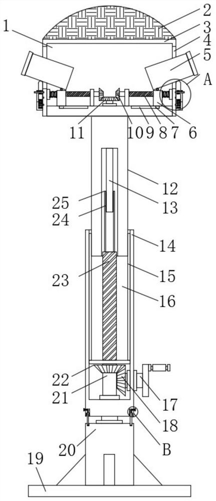
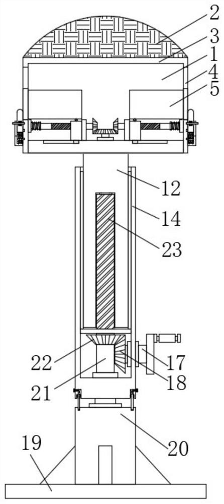
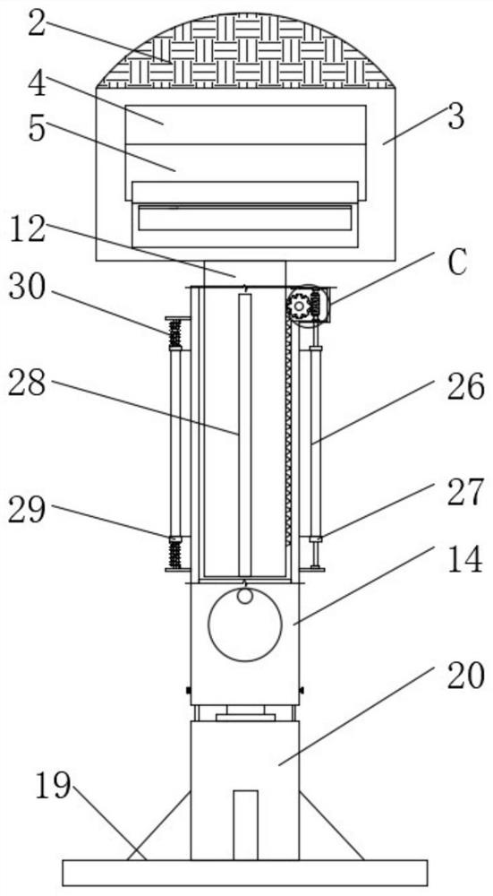
[0038] see Figure 1-6 , the present invention provides a technical solution: a new energy lighting device with storage and angle adjustment functions, including a storage box 3 and a lifting sleeve 14, the inside of the lifting sleeve 14 is provided with a storage groove 16, and the inner wall of the storage groove 16 is set There is a baffle plate, and a power shaft 17 is installed on the inner wall of one side of the storage groove 16 through a rotating bearing,...


PUM


Abstract

The invention discloses a new energy lighting device with storage and angle adjustment functions, and belongs to the technical field of lighting devices. The device comprises a storage box and a lifting sleeve, a storage groove is formed in the lifting sleeve, a baffle is arranged on the inner wall of the storage groove, a power shaft is rotationally installed on the inner wall of one side of the storage groove through a rotating bearing, a first driving bevel gear is fixedly installed at one end of the power shaft, and a rotating disc is fixedly installed at the other end of the power shaft; according to the lighting device, through the arrangement of a first threaded column, a threaded sleeve, a second threaded column, a lifting rod and a sliding rod, after the lighting device is used, the lifting rod can be stored in the lifting sleeve and the lighting lamp can be stored in the storage box only by rotating the rotary disc, and the situation that after a rod body of the lighting device needs to be stored, the lighting lamp needs to be stored again is effectively avoided; or the problems that an existing lighting device is complex to use and large in occupied space with an external protection device, and the height of the lighting device cannot be rapidly adjusted are avoided.

Description

technical field [0001] The invention belongs to the technical field of lighting devices, in particular to a new energy lighting device with functions of storage and angle adjustment. Background technique [0002] New energy, also known as unconventional energy, refers to various energy forms other than traditional energy. Renewable energy, including solar energy, biomass energy, wind energy, geothermal energy, wave energy, ocean current energy and tidal energy, as well as thermal cycles between the ocean surface and deep layers; in addition, there are hydrogen energy, biogas, alcohol, methanol, etc., Energy sources such as coal, oil, natural gas, and water energy that have been widely used are called conventional energy sources. In people's daily life, a large number of lighting devices used are powered by electric energy converted from conventional energy sources. Therefore, a new Energy lighting fixtures. [0003] The existing new energy lighting devices are not equipped...

Claims


Application Information

Patent Timeline
Patent Type & Authority Applications(China)
IPC IPC(8): F21S9/03F21V15/00F21V21/22F21V21/26F21V23/00F21V33/00F21W131/103
CPCY02B20/72
Inventor 金鑫谢翔
Owner 温州企案信息科技有限公司
Why Eureka
Try Eureka