
Numerically-controlled chuck type multi-tool lathe for bearing ring machining

A technology of bearing rings and multi-tool lathes, applied in the field of CNC lathes, can solve the problems of reducing the machining efficiency of lathes, machining accuracy, difficult secondary utilization of lubricating oil, and metal damage of processing equipment, so as to ensure secondary utilization and improve environmental protection Effect, the effect of guaranteeing accuracy

Inactive Publication Date: 2021-04-20
襄阳美金环轴承有限公司
View PDF10 Cites 1 Cited by
  • Summary
  • Abstract
  • Description
  • Claims
  • Application Information

AI Technical Summary

Problems solved by technology

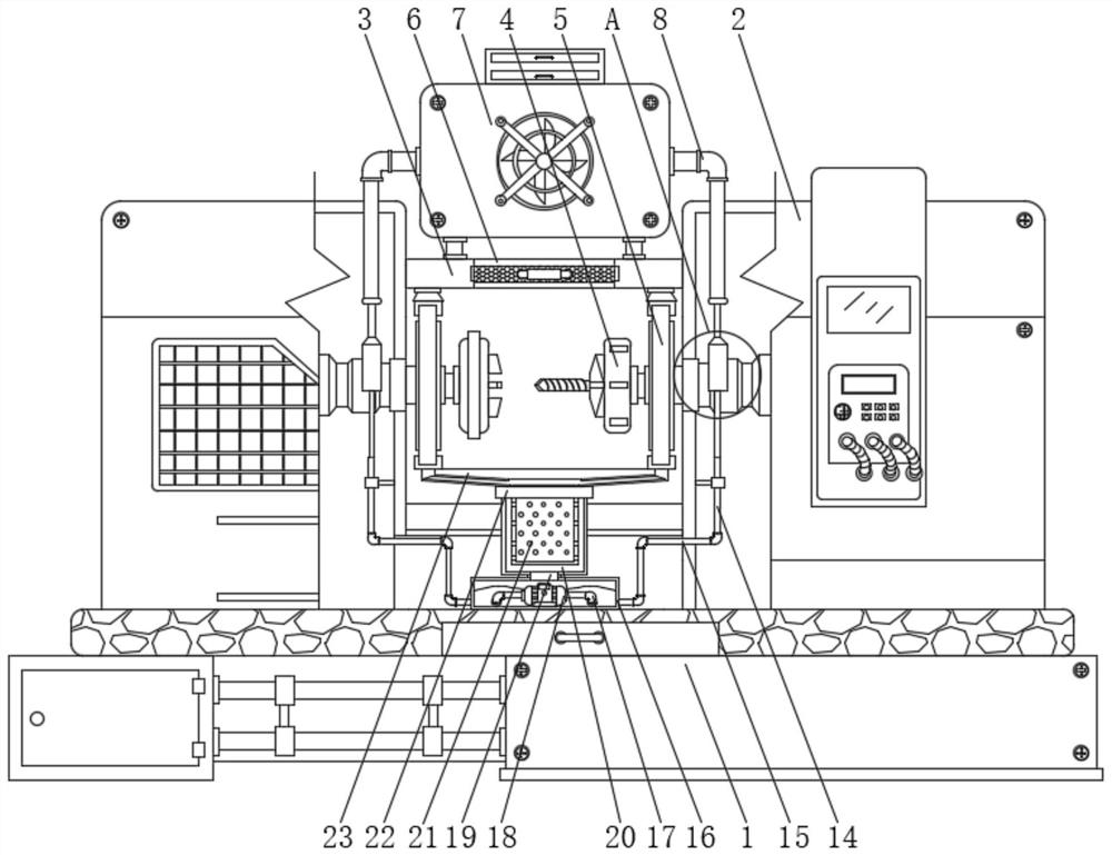
[0005] In order to overcome the above-mentioned defects of the prior art, the present invention provides a multi-cutter lathe with CNC chuck for bearing ring processing. The technical problem to be solved by the present invention is: in the process of using the existing CNC lathe, its internal When the workpiece is processed, a large amount of waste chips will be generated. When the waste chips adhere to the surface of the processing equipment, since the inside of the processing equipment is coated with lubricating oil, a large amount of waste chips will adhere to the surface of the processing equipment under the adhesion of the lubricating oil. Entering the interior of the processing equipment along the lubricating oil will not only cause certain pollution to the lubricating oil, make it difficult to recycle the lubricating oil, but also cause certain damage to the metal inside the processing equipment, thus greatly reducing the processing efficiency of the lathe and The problem of machining accuracy

Method used


Image

  • Numerically-controlled chuck type multi-tool lathe for bearing ring machining
  • Numerically-controlled chuck type multi-tool lathe for bearing ring machining
  • Numerically-controlled chuck type multi-tool lathe for bearing ring machining

Examples


Embodiment Construction

[0026] The following will clearly and completely describe the technical solutions in the embodiments of the present invention with reference to the accompanying drawings in the embodiments of the present invention. Obviously, the described embodiments are only some, not all, embodiments of the present invention. Based on the embodiments of the present invention, all other embodiments obtained by persons of ordinary skill in the art without making creative efforts belong to the protection scope of the present invention.

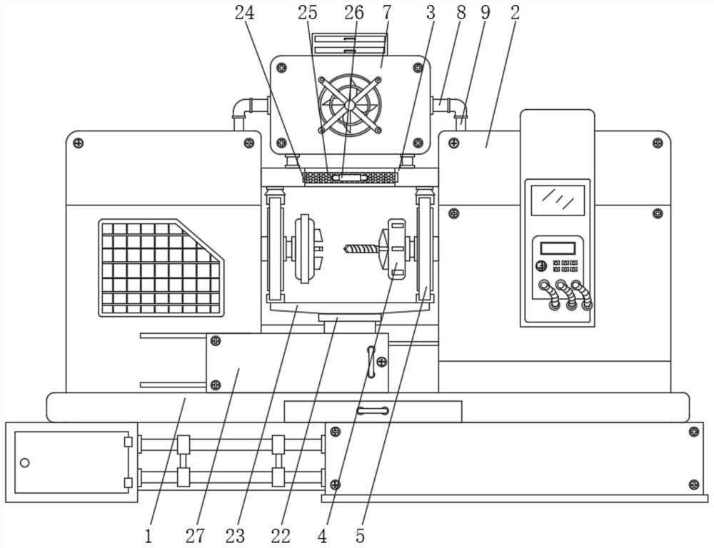
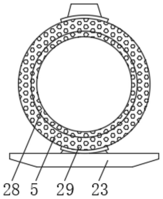
[0027] Such as Figure 1-6 As shown, the present invention provides a kind of numerical control chuck multi-tool lathe for processing bearing rings, comprising a support base 1, the upper surface of the support base 1 is fixedly connected with the lower surfaces of two lathe shells 2, and the two lathe shells The opposite surfaces of the body 2 are respectively fixedly connected with the left and right sides of the connection plate 3, and the two lathe shells ...


PUM


Abstract

The invention discloses a numerically-controlled chuck type multi-tool lathe for bearing ring machining, and specifically relates to the technical field of numerically-controlled lathes. The numerically-controlled chuck type multi-tool lathe for bearing ring machining comprises a supporting base, wherein the upper surface of the supporting base is fixedly connected with the lower surfaces of two lathe shell bodies, and the opposite surfaces of the two lathe shell bodies are fixedly connected with the left side surface and the right side surface of a connecting plate separately; and machining equipment is arranged in each of the two lathe shell bodies. According to the invention, by arranging a separating device, a sponge block, a wind power device and a machining handle, the lathe can synchronously collect waste chips and lubricating oil in a machining process for a workpiece, the lubricating oil and the waste chips can be separated in the collecting process, and therefore the environment-friendly effect of the lathe is improved, and the secondary utilization rate for the lubricating oil by the lathe is guaranteed; and the collected lubricating oil can be discharged into the sponge block, then the lubricating oil is guaranteed to be injected into the machining equipment in time in the operation process of the lathe, and the precision of the lathe while machining the workpiece is guaranteed.

Description

technical field [0001] The invention relates to the technical field of numerically controlled lathes, and more specifically, the invention relates to a multi-tool lathe with numerically controlled chucks for processing bearing rings. Background technique [0002] The spindle of CNC lathe adopts manual control, mechanical and electrical integration design, beautiful appearance, reasonable structure, wide range of uses and convenient operation. Spherical and conical threads and other processes, suitable for mass production. The guide rail of the CNC lathe bed adopts super-audio frequency quenching, advanced technology, strong wear resistance, high precision, advanced spindle system structure, stable speed, and high cutting performance. [0003] Chinese patent literature (CN105436521B) discloses a multi-tool station CNC lathe, which proposes in the specification that "the existing multi-tool station CNC lathe generally includes a workpiece clamping mechanism and a tool clampin...

Claims


Application Information

Patent Timeline
Patent Type & Authority Applications(China)
IPC IPC(8): B23Q11/12B23Q11/00
Inventor 黄光军贾淑成
Owner 襄阳美金环轴承有限公司
Learn More