
Heat exchange device resistant to high temperatures, high pressure and hydrogen corrosion

A technology of heat exchange device and high temperature resistance, applied in heat exchanger sealing device, heat exchange equipment, heat exchanger type, etc., can solve the problem of high purchase cost of reaction heat recovery device, high production cost of heat exchanger, equipment Problems such as high maintenance costs, to avoid excessive temperature rise, reduce production costs, and reduce heat transfer effects

Pending Publication Date: 2021-04-20
NANJING JUTUO CHEM TECH
View PDF0 Cites 2 Cited by
  • Summary
  • Abstract
  • Description
  • Claims
  • Application Information

AI Technical Summary

Problems solved by technology

[0002] At present, the use of heat exchangers to recover the reaction heat of the synthesis gas reaction is more common using tube heat exchangers. Since the temperature of the synthesis gas is high and contains high concentration of hydrogen, in order to ensure the safe operation of the heat exchanger, the equipment It needs to be made of materials resistant to high temperature and strong hydrogen corrosion, which leads to high production costs of heat exchangers and high maintenance costs of equipment, resulting in high purchase costs of reaction heat recovery devices

Method used


Image

  • Heat exchange device resistant to high temperatures, high pressure and hydrogen corrosion
  • Heat exchange device resistant to high temperatures, high pressure and hydrogen corrosion
  • Heat exchange device resistant to high temperatures, high pressure and hydrogen corrosion

Examples


Embodiment Construction

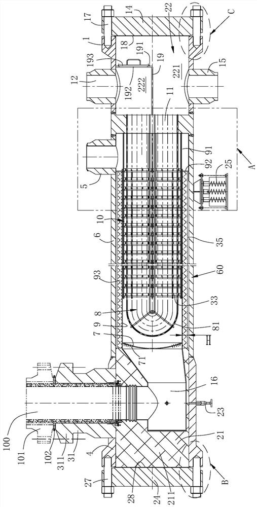
[0033] see figure 1 , a heat exchange device resistant to high temperature, high pressure, and hydrogen corrosion, which includes a shell, a tube plate 11 arranged in the shell, the shell includes a cylinder 60, and first sealing flat covers 24 arranged at both ends of the cylinder And the second sealing flat cover 14, the tube plate 11 divides the inner cavity of the shell into a heat exchange cavity 21 and a refrigerant cavity 22, wherein the heat exchange cavity is located between the tube plate 11 and the first flat cover 24, and the refrigerant cavity is located between the tube plate 11 and the second flat cover 14. The shell is horizontal, the first flat cover 24 is installed on the barrel through the first bolt 17 , and the second flat cover 14 is installed on the barrel through the second bolt 27 .

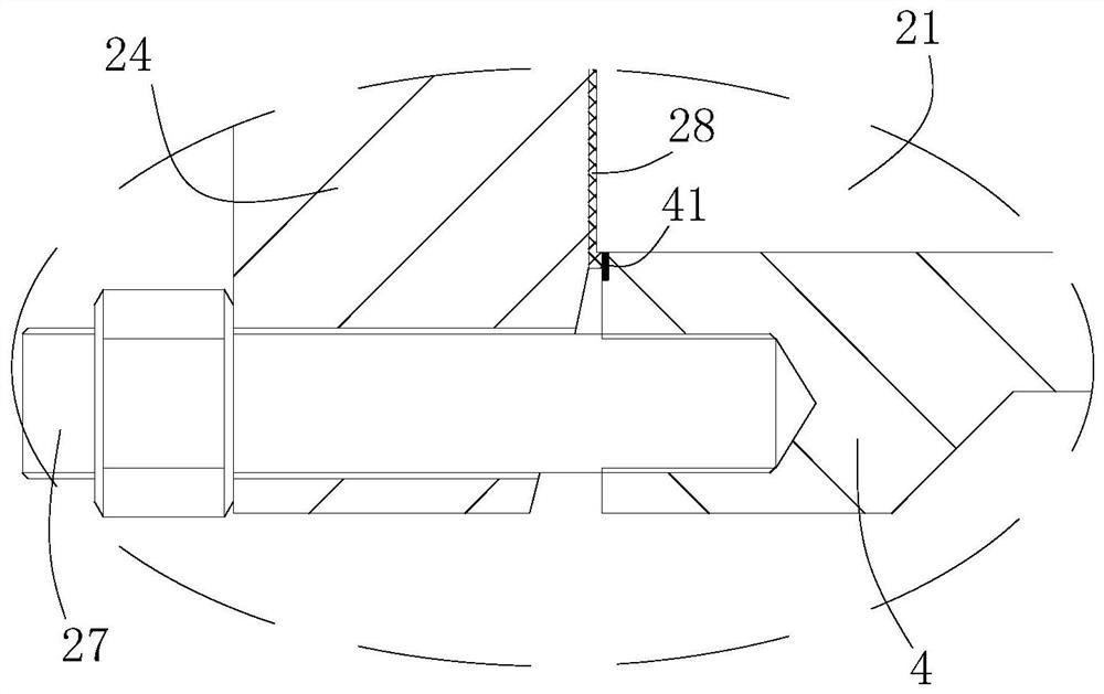
[0034] see image 3A first sealing diaphragm 28 is installed between the first flat cover 24 and the cylinder 60, the first sealing diaphragm 28 completely isolates the...


PUM


Abstract

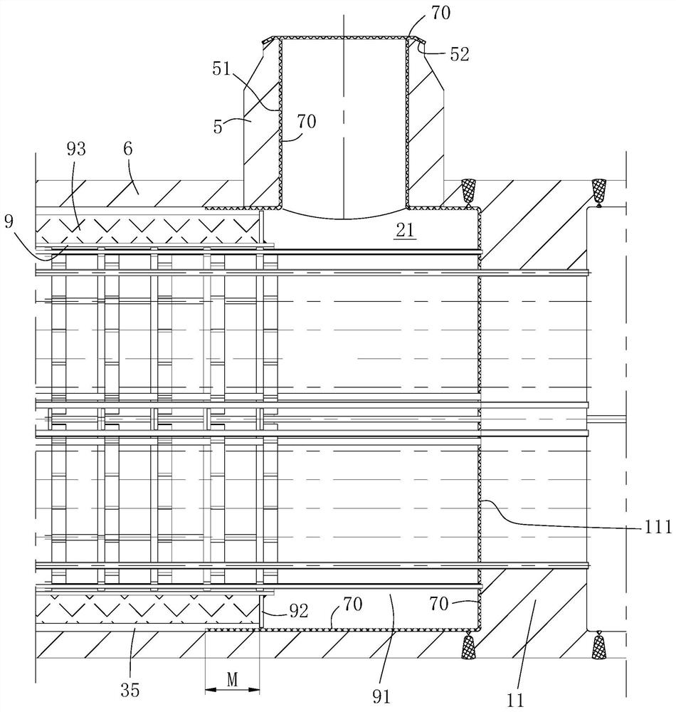
The invention discloses a heat exchange device resistant to high temperatures, high pressure and hydrogen corrosion. The device comprises a shell and a tube plate arranged in the shell, and an inner cavity of the shell is divided into a heat exchange cavity and a refrigerant cavity by the tube plate. The refrigerant cavity is divided into a liquid inlet cavity and a liquid outlet cavity. A heat insulation cylinder and a high-temperature inner header are installed in the heat exchange cavity, and the two ends of a U-shaped heat exchange pipe are communicated with the liquid inlet cavity and the liquid outlet cavity through the tube plate. A communicating part for communicating the inside and outside of the heat insulation cylinder is arranged between the heat insulation cylinder and the tube plate. The high-temperature inner header is communicated with the heat insulation cylinder. A gas inlet pipe and a gas outlet pipe are arranged on the shell, the gas inlet pipe directly faces the high-temperature inner header and is communicated with the high-temperature inner header, and the gas outlet pipe directly faces the communicating part. A first heat preservation material is filled between the high-temperature inner header and the shell, an annular gap between the heat insulation cylinder and a cylinder body forms a dead gas area, and the dead gas area is communicated with an inner cavity of the heat insulation cylinder through the communicating part. By means of the heat exchange device, the manufacturing cost of equipment can be well reduced.

Description

technical field [0001] The invention belongs to the technical field of chemical equipment, in particular to a heat exchange device resistant to high temperature, high pressure and hydrogen corrosion. Background technique [0002] At present, the use of heat exchangers to recover the reaction heat of the synthesis gas reaction is more common using tube heat exchangers. Since the temperature of the synthesis gas is high and contains high concentration of hydrogen, in order to ensure the safe operation of the heat exchanger, the equipment It needs to be made of materials that are resistant to high temperature and strong hydrogen corrosion, which leads to high production cost of the heat exchanger and high maintenance cost of the equipment, resulting in high purchase cost of the reaction heat recovery device. Contents of the invention [0003] Aiming at the problem of high manufacturing cost of existing reaction heat recovery devices, this application proposes a heat exchange ...

Claims


Application Information

Patent Timeline
Patent Type & Authority Applications(China)
IPC IPC(8): F28D7/06F28F9/00F28F9/22F28F11/02F28F21/08
Inventor 卢健陈兆董超张海艳钱丽
Owner NANJING JUTUO CHEM TECH
Learn More