Photoelectric signal switching connector

A technology for switching connectors and optoelectronic signals, which is applied in the direction of connection, parts and circuits of connecting devices, and can solve the problems of inability to meet the requirements of miniaturization of equipment and use in harsh environments, poor strength and stability, etc.

Active Publication Date: 2021-04-20
遵义市飞宇电子有限公司
View PDF10 Cites 0 Cited by
  • Summary
  • Abstract
  • Description
  • Claims
  • Application Information

AI Technical Summary

Problems solved by technology

[0005] The general photoelectric signal transfer connector shell is made of plastic, with poor strengt

Method used


Image

  • Photoelectric signal switching connector
  • Photoelectric signal switching connector
  • Photoelectric signal switching connector

Examples


Embodiment 1

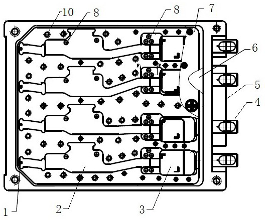
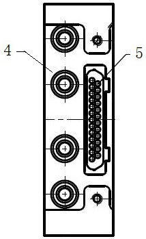
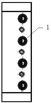
[0032] Such as Figure 1-11 , a photoelectric signal transfer connector, including a box body, an electrical connector 1 and an optical connector 4, the box body is made of metal, and a conversion cavity and a control cavity are arranged on the box body, and the conversion cavity A converter installation position is provided, a conversion controller is provided in the control chamber, a glass-sealed welding pin 8 is provided between the conversion chamber and the control chamber, and the bottom surface of the converter installation position is provided with a The heat conduction block 9 on the outside of the box body, and the control connector 5 is also provided on the box body. The material of the heat conduction block 9 is tungsten copper, and the material of the box body is copper. After the surface of the box body is electroplated with nickel, it is welded with the heat conduction block 9 by silver-copper solder, and then the surface is plated with gold.

[0033] Such as ...

Embodiment 2

[0040] The leakage rate of said electrical connector 1 in the connector is lower than 1X10 -3 Pa.cm 3 / S. The insulation resistance between the pins 8 is greater than 1000MΩ (500V-DC), and the dielectric withstand voltage is greater than 500V.

[0041] The surface of the heat conducting block 9 is required to be flat and smooth. The outer side of the control connector 5 is in the shape of a jack, and the inner side is in the shape of a pin. There are 20-30 control signals in the control connector 5, corresponding to four groups of photoelectric conversion.

[0042] Such as Figure 9 , the pressing plate 7 in the transition cavity can be set as multi-layers, and for more transition cavity components, they are respectively fixed, and after fixing, it is convenient to weld and seal the cover plate. The box body, the pressing plate 7 and the inner surface of the cover plate are provided with 0.5mm deep milling grooves to facilitate the placement or spacing of internal componen...


PUM

PropertyMeasurementUnit
Wavelengthaaaaaaaaaa
Insulation resistanceaaaaaaaaaa

Abstract

The invention discloses a photoelectric signal switching connector, which belongs to the technical field of electronics and comprises a box body, an electric connector and an optical connector, wherein the box body is made of a metal material and is provided with a conversion cavity and a control cavity, a device mounting position is arranged in the conversion cavity, and a glass-sealed and welded contact pin is arranged between the conversion cavity and the control cavity. A heat conduction block extending to the outer side of the box body is arranged on the bottom face of the device mounting position of the conversion cavity, and a control connector is further arranged on the box body. The shell of the connector is made of copper and is provided with layers, the lead is welded by glass sealing, the connector is high in strength, the appearance of the connector is only 58mm*45mm*13mm, and the connector can be used for conversion of four groups of high-speed signals. The connector is reasonable in design, strong in interference resistance, high in signal quality and good in heat conduction performance; the device has the remarkable advantages of small size, high conversion quality and high applicable power, and can be used in special fields such as spaceflight, aviation or military.

Description

technical field [0001] The invention relates to the field of electrical connectors, in particular to a photoelectric signal transfer connector. Background technique [0002] Optical fiber communications technology (optical fiber communications) is one of the main pillars of modern communications, and it is used in telecommunication networks, aerospace, aviation, and military fields. The rapid development and wide application of optical fiber communication in recent years are rare in the history of communication. It is an important symbol of the world's new technological revolution and the main transmission tool for various information in the future information society. [0003] Optical fiber is the abbreviation of optical fiber. Optical fiber communication is a communication method in which light waves are used as information carriers and optical fibers are used as transmission media. In principle, the basic material elements that constitute optical fiber communication are...

Claims


Application Information

Patent Timeline
IPC IPC(8): G02B6/42H01R13/52H01R13/6581H01R31/06
Inventor 苏勇潘亚楠向伟明
Owner 遵义市飞宇电子有限公司
Why Eureka
Try Eureka