Underwater wireless light emitting system, underwater wireless light emitting method and underwater wireless light communication system

A transmission system and wireless optical technology, which is applied in the field of underwater wireless optical transmission system and underwater wireless optical communication system, can solve the problems of inability to guarantee optical signal attenuation loss, communication performance impact, and reduce system data transmission efficiency. Underwater wireless optical communication, high-quality underwater wireless optical communication, and the effect of improving transmission efficiency

Pending Publication Date: 2021-04-20
XIAN UNIV OF POSTS & TELECOMM
View PDF0 Cites 5 Cited by
  • Summary
  • Abstract
  • Description
  • Claims
  • Application Information

AI Technical Summary

Problems solved by technology

However, when only one working wavelength is used for underwater wireless information transmission, it cannot guarantee that the optical signal has a small attenuation loss in different seawater channels, which reduces the system data transmission efficiency, leads to poor system adaptability, and affects communication performance. Serious impact

Method used


Image

  • Underwater wireless light emitting system, underwater wireless light emitting method and underwater wireless light communication system
  • Underwater wireless light emitting system, underwater wireless light emitting method and underwater wireless light communication system
  • Underwater wireless light emitting system, underwater wireless light emitting method and underwater wireless light communication system

Examples


Embodiment Construction

[0040] Example embodiments will now be described more fully with reference to the accompanying drawings. Example embodiments may, however, be embodied in many forms and should not be construed as limited to the examples set forth herein; rather, these embodiments are provided so that this disclosure will be thorough and complete and fully convey the concept of example embodiments to those skilled in the art. The described features, structures, or characteristics may be combined in any suitable manner in one or more embodiments.

[0041] In addition, the drawings are merely schematic illustrations of embodiments of the present invention and are not necessarily drawn to scale. The same reference numerals in the drawings denote the same or similar parts, and thus repeated descriptions thereof will be omitted. Some of the block diagrams shown in the drawings are functional entities and do not necessarily correspond to physically or logically separate entities.

[0042] In this ...


PUM


Abstract

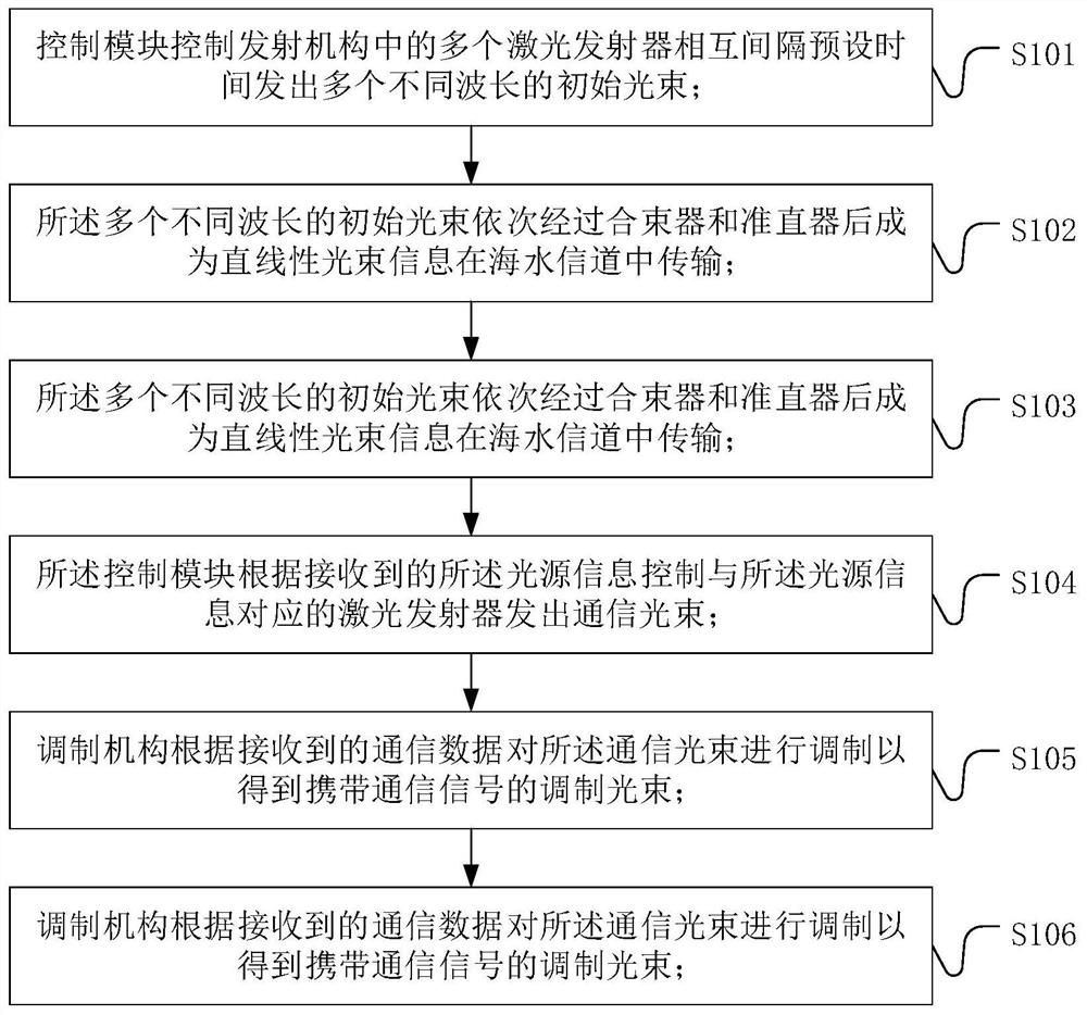
The embodiment of the invention relates to an underwater wireless light emitting system, an underwater wireless light emitting method and an underwater wireless light communication system. The device comprises: an emission mechanism which comprises a plurality of laser emitters emitting laser with different wavelengths; a multimode fiber combiner; an optical fiber collimator which adjusts the light beam into a linear light beam signal and sends out the linear light beam signal; a control module which is used for controlling the plurality of laser emitters to emit a plurality of initial light beams with different wavelengths at preset intervals; a photoelectric power detector which receives the initial light beams, obtains light source information corresponding to the initial light beam with the maximum power value and sends the light source information to the control module, wherein the control module controls the corresponding laser emitter to emit a communication light beam; and a modulation mechanism which is used for receiving the communication data and modulating the communication light beam to obtain a modulated light beam carrying a communication signal. According to the embodiment of the invention, the transmission performance of different optical wavelengths in different seawater environments is utilized, and the optical wavelength with the minimum absorption and scattering loss after output is selected as a communication light source for different seawater environments, so that the transmission efficiency is improved, and high-quality communication is realized.

Description

technical field [0001] Embodiments of the present invention relate to the technical field of underwater wireless communication, in particular to an underwater wireless optical transmission system, method and underwater wireless optical communication system. Background technique [0002] As people pay more and more attention to the development of marine resources, underwater communication technology has become a key technology for people to explore the ocean. At present, underwater communication technology mainly includes sound waves, RF waves, and light waves to realize data transmission. Compared with sound waves and RF wave communications, light waves are used as underwater information transmission carriers, which have strong anti-interference ability, fast transmission rate, and large amount of information. Therefore, underwater wireless optical communication technology has a wide range of applications in resource exploration, environmental monitoring, and underwater robo...

Claims


Application Information

Patent Timeline
Patent Type & Authority Applications(China)
IPC IPC(8): H04B10/50H04B10/80
Inventor 贺锋涛杨祎李佳琪
Owner XIAN UNIV OF POSTS & TELECOMM
Why Eureka
Try Eureka