Annealing piece stamping and shearing die capable of conveniently reducing cutting resistance

A punching, shearing and annealing technology, applied in forming tools, manufacturing tools, springs/shock absorbers, etc., can solve the problem of inconvenient annealing belt limit conveying and uniform application of stamping oil, inconvenience in buffering, cooling protection and replacement, inconvenience in annealing problems such as chip and waste collection, to achieve the effect of long service life, easy collection, and reduced resistance

Pending Publication Date: 2021-04-23
芜湖品金电器科技有限公司
View PDF0 Cites 1 Cited by
  • Summary
  • Abstract
  • Description
  • Claims
  • Application Information

AI Technical Summary

Problems solved by technology

[0004] The purpose of the present invention is to provide an annealed sheet stamping and shearing die which can reduce the cutting resistance conveniently, so as to solve the problem that the existing annealing sheet stamping and shearing die proposed in the above-mentioned background technology is generally inconvenient to carry out limit delivery and uniform Applying stamping oil, high cutting resistance, low stamping shear efficiency, inconvenient buffering, cooling protection and replacement, short service life, and inconvenient collection of annealed sheets and waste after stamping and shearing

Method used


Image

  • Annealing piece stamping and shearing die capable of conveniently reducing cutting resistance
  • Annealing piece stamping and shearing die capable of conveniently reducing cutting resistance
  • Annealing piece stamping and shearing die capable of conveniently reducing cutting resistance

Examples


Embodiment Construction

[0029] The following will clearly and completely describe the technical solutions in the embodiments of the present invention with reference to the accompanying drawings in the embodiments of the present invention. Obviously, the described embodiments are only some, not all, embodiments of the present invention. Based on the embodiments of the present invention, all other embodiments obtained by persons of ordinary skill in the art without making creative efforts belong to the protection scope of the present invention.

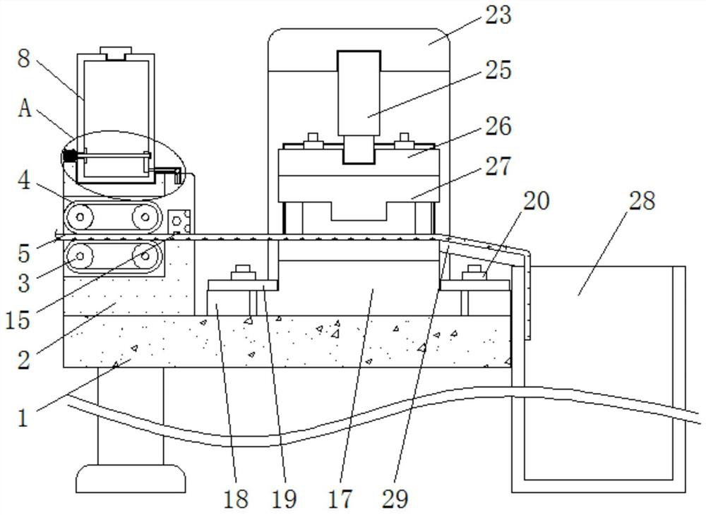
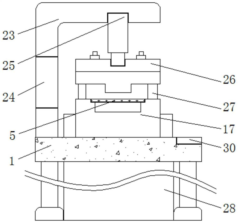
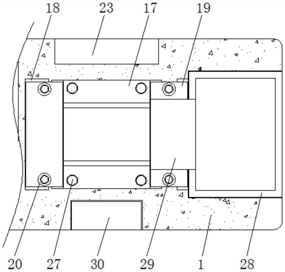
[0030] see Figure 1-7 , the present invention provides a technical solution: a stamping and shearing die for annealed sheet that is convenient for reducing cutting resistance, including a base 1, a connecting plate 2, a limit rod 3, a belt 4, an annealing belt 5, a shaft gear 6, a first Motor 7, oil tank 8, movable rod 9, second motor 10, first gasket 11, second gasket 12, transparent plate 13, multi-way pipe 14, limiting plate 15, sponge 16, lower mold 17, f...


PUM


Abstract

The invention discloses an annealing piece stamping and shearing die capable of conveniently reducing cutting resistance. The annealing piece stamping and shearing die comprises a base and a lower die body, a connecting plate and a supporting plate are fixedly connected to the upper surface of the left end and the upper surface of the middle of the front end of the base respectively, a belt is connected to the outer side of the middle of a limiting rod in an attached mode, a shaft-provided gear is fixedly connected to the front side of the limiting rod, an oil containing tank is connected to the inner side of the upper end of the connecting plate in an embedded mode, an output shaft of a second motor is connected to the left side of a movable rod, and a transparent plate is connected to the inner side of the rear end of the oil containing tank in an embedded mode. According to the annealing piece stamping and shearing die capable of conveniently reducing the cutting resistance, limiting conveying and uniform stamping oil smearing can be conveniently conducted on an annealing belt, the resistance of cutting the annealing belt is reduced, the stamping and shearing efficiency is high, buffering, cooling protection and replacement can be conveniently conducted on the lower die body and an upper die body, the service life of the stamping and shearing die is long, and the punched and sheared annealing pieces and waste materials can be conveniently collected.

Description

technical field [0001] The invention relates to the technical field of stamping and shearing dies for annealed sheets, in particular to a stamping and shearing die for annealed sheets that is convenient for reducing cutting resistance. Background technique [0002] The annealed sheet is a high-flux sheet with low heat generation and large inductance. It is widely used in many fields such as integrated circuits, discrete devices, and solar energy. In the process of manufacturing annealed sheets, it is often necessary to press and shear the annealed sheet. Punch shearing to form an annealed sheet; [0003] Existing stamping and shearing dies for annealed sheet are generally inconvenient for limited conveying of annealed strips and uniform application of stamping oil, high cutting resistance, low stamping and shearing efficiency, inconvenient buffering, cooling protection and replacement, and short service life. And it is not convenient to collect the annealed sheet and waste ...

Claims


Application Information

Patent Timeline
Patent Type & Authority Applications(China)
IPC IPC(8): B21D28/14B21D28/02B21D43/12B21D37/18B21D37/04B21D43/20B21D45/00B21D37/16F16F15/067
CPCB21D28/02B21D28/14B21D37/04B21D37/16B21D37/18B21D43/12B21D43/20B21D45/00F16F15/067
Inventor 阮新贵
Owner 芜湖品金电器科技有限公司
Why Eureka
Try Eureka