Blanket dyeing device and dyeing method

A dyeing device and dyeing method technology, applied in the processing of textile material equipment configuration, textile and papermaking, liquid/gas/steam textile processing, etc. High operability, overcoming color flower, simple and practical effect of installation

Pending Publication Date: 2021-04-23
LOFTEX INDS
View PDF6 Cites 2 Cited by
  • Summary
  • Abstract
  • Description
  • Claims
  • Application Information

AI Technical Summary

Problems solved by technology

[0003] Aiming at the technical problems existing at present, the present invention provides a blanket dyeing device and dyeing method, which can solve the

Method used


Image

  • Blanket dyeing device and dyeing method
  • Blanket dyeing device and dyeing method
  • Blanket dyeing device and dyeing method

Examples


Embodiment 1

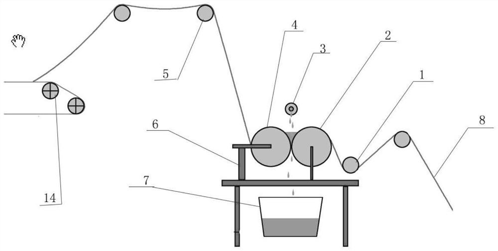
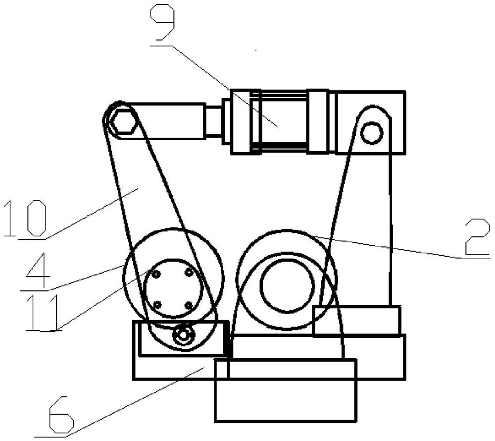
[0025] As shown in the figure, a kind of blanket dyeing device provided by the present invention includes a cloth-in traction device 1, a cloth-out traction device 5, a drying device 14, a frame 6, a pulping device and a pulping device; a cloth-in traction device 1 It includes a cloth-feeding traction roller and a spreading roller driven by a motor. The press device includes a driving roller 2 and a pressure roller 4. The driving roller 2 and the pressure roller 4 are arranged in parallel. The distance between the driving roller 2 and the pressure roller 4 is 0-8cm. The driving roller 2 is arranged on the frame 6, the rotating rod of the driving roller 2 is connected to the motor, the two ends of the pressure roller 4 are connected to the middle and lower end of the handle 10 through the bearing 11, the lower end of the handle 10 is connected to the frame 6 through a stud, and the upper end of the handle 10 is connected to the frame through a screw. The column is connected to t...

Embodiment 2

[0027] A dyeing method utilizing a blanket dyeing device, the specific method is as follows:

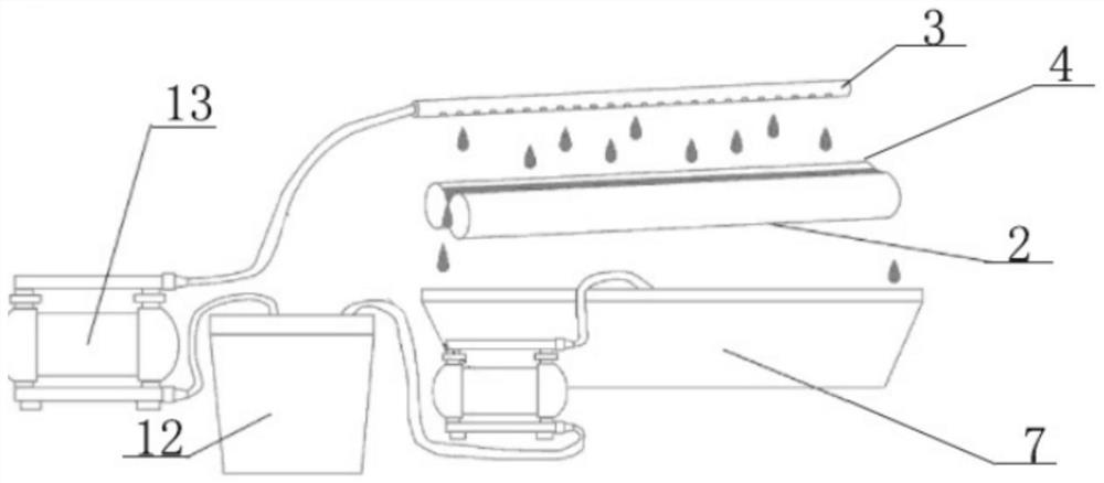
[0028] The blanket gray cloth 8 is drawn by the cloth-entry traction device 1 to the top of the driving roller 2, wraps around the driving roller 2, and then comes out from the bottom of the pressure roller 4, and reaches the drying device 14 through the cloth-out traction device 5; the connecting rod of the control cylinder 9 is elongated, The connecting rod control handle 10 drives the pressure roller 4 close to the driving roller 2, so that the groove formed by the pressure roller 4, the gray cloth 8 and the driving roller 2, the distance between the driving roller 2 and the pressure roller 4 is 6 mm, and the driving roller 2 and the pressure roller 4 The pressure between the gray cloth 8 is 0.45MPa; open the suction pump, the flow rate of the suction pump is 9m 3 / h, so that the spray pipe 3 sprays the slurry into the groove through the slurry outlet, fills the groove, turns on t...

Embodiment 3

[0030] A dyeing method utilizing a blanket dyeing device, the specific method is as follows:

[0031] The blanket gray cloth 8 is drawn by the cloth-entry traction device 1 to the top of the driving roller 2, wraps around the driving roller 2, and then comes out from the bottom of the pressure roller 4, and reaches the drying device 14 through the cloth-out traction device 5; the connecting rod of the control cylinder 9 is elongated, The connecting rod control handle 10 drives the pressure roller 4 close to the driving roller 2, so that the groove formed by the pressure roller 4, the gray cloth 8 and the driving roller 2, the distance between the driving roller 2 and the pressure roller 4 is 4mm, and the driving roller 2 and the pressure roller 4 The pressure between the gray cloth 8 is 0.25MPa; open the suction pump, the flow rate of the suction pump is 6m 3 / h, so that the spray pipe 3 sprays the slurry into the groove through the slurry outlet hole, fills the groove, turns ...


PUM


Abstract

The invention belongs to the technical field of blanket production, and particularly relates to a blanket dyeing device and dyeing method. The device comprises a size adding device and a size pressing device, wherein the paste pressing device comprises a driving roller and a pressure roller, the driving roller and the pressure roller are arranged in parallel, the driving roller is arranged on a rack, a rotating rod of the driving roller is connected with a motor, and a material receiving groove is formed below the driving roller and the pressure roller; squeezing sizing of grey cloth is realized through the size pressing device, so that the size carrying rate of the grey cloth is 80-120%; redundant size flows out from two ends of the groove and falls into a size tank below, and the size in the size tank is conveyed into a size barrel to be uniformly mixed with new size for continuous use. According to the blanket dyeing device and dyeing method, the dyeing defect caused by migration of dye in the color paste is effectively overcome, the blanket production quality and efficiency are greatly improved, and the device is simple, practical, high in operability and remarkable in effect.

Description

technical field [0001] The invention belongs to the technical field of blanket production, and in particular relates to a blanket dyeing device and a dyeing method. Background technique [0002] At present, the traditional pad dyeing device for producing plain blankets is equipped with a slurry tank, and the slurry is injected into the tank in advance. When the gray cloth passes through the slurry tank, it is soaked in the slurry tank for 1 or 2 times, and then the gray cloth is soaked by pressing rollers. Roll off the excess slurry, and then carry out coloring and color fixing treatment through drying, color fixing and other production processes. Due to changes in the concentration of dyes and the migration of dye particles, there may be color differences between the dyed fabrics before and after, left and right, and between them, which is difficult to control. Contents of the invention [0003] Aiming at the technical problems existing at present, the present invention ...

Claims


Application Information

Patent Timeline
IPC IPC(8): D06B1/14D06B23/02D06B23/20
CPCD06B1/145D06B1/148D06B23/021D06B23/20
Inventor 王红星
Owner LOFTEX INDS
Why Eureka
Try Eureka