Anti-seismic connecting structure for fabricated steel-concrete composite beam

A steel-concrete composite beam and connection structure technology, which is applied to bridges, bridge parts, bridge construction, etc., can solve problems such as long cycle time, corrosion, and difficult quality assurance

Pending Publication Date: 2021-04-23
CHONGQING JIAOTONG UNIVERSITY +2
View PDF2 Cites 0 Cited by
  • Summary
  • Abstract
  • Description
  • Claims
  • Application Information

AI Technical Summary

Problems solved by technology

Common shear connectors mainly include four types of steel bar connectors, steel connectors, PBL connectors and stud connectors; among them, stud connectors and PBL connectors are currently the most widely used in engineering; PBL connectors are mainly The longitudinal shear force is resisted through the concrete tenons and through-bars in the openings. The through-bars set in the openings can greatly increase the ultimate bearing capacity of the connectors. However, due to the need to arrange through-bars in the holes, construction brings It is very inconvenient, and the production process is time-consuming and labor-intensive; the stud connectors need to reserve holes for concrete pouring, which will make the shear force transmission between the steel-concrete interface discontinuous, and there will be split areas in the concrete slab. The amount of concrete poured in the force slots is small, the number of shear slots is large, and the quality is not easy to guarantee; this will lead to poor integrity of the bridge deck, and at the same time, the quality of wet joint concrete is not easy to guarantee, and the interface between new and old concrete is also prone to cracking; To sum up, the existing connection methods require more concrete pouring processes, and the on-site construction period is longer, which is not conducive to the rapid construction of steel-concrete composite structures.
[0003] Chinese patent No. CN201510618404.1 proposes a new type of concrete slab with a channel at the bottom. A new type of self-locking steel-concrete connector can be formed by setting a channel at the bottom of the concrete bridge deck to match the steel beam. Although the technology effectively solves the problems of steel-concrete joint surface corrosion, concrete cracking, and the quality of post-cast concrete is difficult to control, but this technology mainly relies on the bonding force and friction between the connector and the mortar to resist shear force. prone to damage
[0004] Chinese patent No. CN201620452745.6 proposes a perforated plate connector with a shoe-shaped slot hole, a steel beam and an anisotropic steel plate. One side of the perforated plate connector has a straight profile, and the other side of the perforated plate connector Protruding connectors and recessed slots are repeatedly arranged on the side, and the recessed slots are shoe-shaped; after the shape of the protruding connectors is rotated 180°, it is consistent with the shape and size of the recessed slots; the two pieces are the same The size of the open-hole plate connector, after one of them is rotated 180°, the protruding connectors and the recessed slots of the two just fit and dock, and the buckle is a complete strip; although this utility model effectively solves the problem of The process of arranging steel bars interspersed reduces manpower input, but this utility model still does not get rid of the construction process of arranging steel bars on connectors and cast-in-place concrete bridge decks, and is still not suitable for bridges that require rapid construction

Method used


Image

  • Anti-seismic connecting structure for fabricated steel-concrete composite beam
  • Anti-seismic connecting structure for fabricated steel-concrete composite beam
  • Anti-seismic connecting structure for fabricated steel-concrete composite beam

Examples


Embodiment Construction

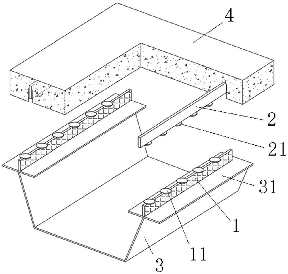
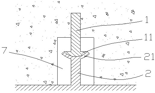
[0017] An anti-seismic coupling structure for prefabricated steel-concrete composite girders, including steel box girders and concrete bridge decks, both of which are prefabricated, and its innovation lies in: the two steel box girders Each flange plate is provided with a first connecting ridge 1, the axial direction of the first connecting ridge 1 is parallel to the axial direction of the flange plate, and the length of the first connecting ridge 1 is equal to the length of the flange plate; The upper end surface of the ridge 1 is provided with a plurality of semicircular grooves, and a female part 11 is arranged in each semicircular groove; The diameter is greater than the thickness of the first connecting ridge 1;

[0018] The lower side of the concrete bridge deck is provided with two grooves, the grooves are connected to the front and rear end faces of the concrete bridge deck; the axial direction of the groove is parallel to the axial direction of the concrete bridge dec...


PUM


Abstract

The invention discloses an anti-seismic connecting structure for a fabricated steel-concrete composite beam; theanti-seismic connecting structure comprises a steel box beam and a concrete bridge deck slab, and two flange plates of the steel box beam are respectively provided with first connecting ridges; a plurality of female parts are arranged on the upper end surface of each first connecting ridge; two grooves are formed in the lower side surface of the concrete bridge deck slab; second connecting ridges are arranged at the bottoms of the grooves, and a plurality of male parts are arranged on the lower end face of each second connecting ridge; during assembly, the concrete bridge deck slab is placed on the flange plate of the steel box girder, the lower end face of the concrete bridge deck slab makes contact with the upper end face of the flange plate, and the male parts are inserted into the female parts in a one-to-one correspondence mode. The anti-seismic connecting structure for the fabricated steel-concrete composite beam has the beneficial technical effects that the anti-seismic connecting structure for the fabricated steel-concrete composite beam is provided, the scheme is convenient to construct, the anti-shear bearing capacity of the structure can be effectively improved, and the effect of absorbing seismic energy through sliding can be achieved after a bonding body is damaged.

Description

technical field [0001] The invention relates to a bridge structure, in particular to an anti-seismic connection structure for an assembled steel-concrete composite beam. Background technique [0002] In the steel-concrete composite girder bridges in the prior art, the concrete bridge deck and the steel box girder are generally connected into one body through shear connectors to participate in the stress-bearing process of the structure. Common shear connectors mainly include four types of steel bar connectors, steel connectors, PBL connectors and stud connectors; among them, stud connectors and PBL connectors are currently the most widely used in engineering; PBL connectors are mainly The longitudinal shear force is resisted through the concrete tenons and through-bars in the openings. The through-bars set in the openings can greatly increase the ultimate bearing capacity of the connectors. However, due to the need to arrange through-bars in the holes, construction brings I...

Claims


Application Information

Patent Timeline
IPC IPC(8): E01D19/00E01D2/04E01D19/12
CPCE01D19/00E01D2/04E01D19/12E01D19/125
Inventor 胡俊俞登荣谭少华严春明梁超贤周玉坤徐俊欣范传振
Owner CHONGQING JIAOTONG UNIVERSITY
Why Eureka
Try Eureka