
An ultrasonic residual stress detection system and measurement method

A residual stress and detection system technology, applied in force/torque/work measuring instruments, measuring force, measuring devices, etc., can solve the problem of affecting the test accuracy of ultrasonic residual stress testing methods, limiting the development of ultrasonic residual stress testing methods, and critical refraction longitudinal waves. The first critical angle is different and other problems, so as to reduce the impact, reduce the production cost, and achieve the effect of simple and convenient operation.

Active Publication Date: 2022-03-29
CRRC QINGDAO SIFANG CO LTD
View PDF0 Cites 0 Cited by
  • Summary
  • Abstract
  • Description
  • Claims
  • Application Information

AI Technical Summary

Problems solved by technology

The influence of some influencing factors on the ultrasonic propagation velocity is even in the same order of magnitude as that of the welding residual stress on the ultrasonic propagation velocity, which seriously affects the test accuracy of the ultrasonic residual stress test method and limits the development of the ultrasonic residual stress test method.
Moreover, the difference in material structure will also lead to the difference in the first critical angle for exciting the critical refracted longitudinal wave. In the prior art, the first critical angle calculated based on the base metal is used to detect the residual stress in different regions of the weldment to be tested, and there must be a large measurement error

Method used


Image

  • An ultrasonic residual stress detection system and measurement method
  • An ultrasonic residual stress detection system and measurement method
  • An ultrasonic residual stress detection system and measurement method

Examples


Embodiment Construction

[0059] It should be noted that the following detailed description is exemplary and intended to provide further explanation of the present invention. Unless defined otherwise, all technical and scientific terms used herein have the same meaning as commonly understood by one of ordinary skill in the art to which this invention belongs.

[0060] It should be noted that the terminology used here is only for describing specific embodiments, and is not intended to limit exemplary embodiments according to the present invention. As used herein, unless the invention clearly states otherwise, the singular form is also intended to include the plural form. In addition, it should also be understood that when the terms "comprising" and / or "comprising" are used in this specification, their Indicate the presence of features, steps, operations, means, components and / or combinations thereof;

[0061] For the convenience of description, if the words "up", "down", "left" and "right" appear in th...


PUM


Abstract

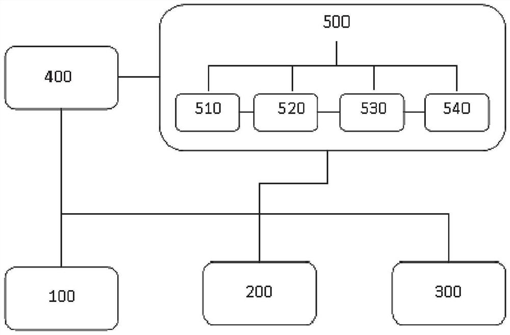
The invention discloses an ultrasonic residual stress detection system and a measurement method. The detection system includes a residual stress detection unit, an acoustic anisotropy detection unit and an attenuation test unit. The emission probe for residual stress detection in the residual stress detection unit is and the receiving probe, the longitudinal wave plane probe of the attenuation test unit and the shear wave probe of the acoustic anisotropy detection unit are all electrically connected to the multi-channel ultrasonic card and the data processing center, and the data processing center includes a database module, an orientation azimuth angle determination module, The longitudinal wave attenuation calculation module and the residual stress calculation module; the ultrasonic residual stress detection system can perform acoustic anisotropy detection and attenuation test on the weldment to be tested, and can realize the residual stress detection in different directions in the same measurement area, so as to obtain the two dimensions of the test area. The three-dimensional plane stress field, and the system can reduce the influence of the material structure effect, and greatly improve the measurement accuracy of the ultrasonic testing method.

Description

technical field [0001] The invention relates to the field of welding residual stress detection, and specifically discloses an ultrasonic residual stress detection system and a measurement method. Background technique [0002] The statements herein merely provide background information related to the present invention and do not necessarily constitute prior art. [0003] Welding is the most important connection method in industrial production. The quality of welding determines the quality of welding products. The damage of welded joints caused by excessive welding residual stress is the most important welding damage. The non-destructive testing of residual stress of welded joints plays a very important guiding role in optimizing the welding process in production practice. The non-destructive testing methods for residual stress mainly include neutron diffraction method, synchrotron radiation method, magnetic particle method, X-ray diffraction method and ultrasonic testing met...

Claims


Application Information

Patent Timeline
Patent Type & Authority Patents(China)
IPC IPC(8): G01L5/00G01L1/25
CPCG01L5/0047G01L1/255
Inventor 刘建张风东邢艳双盖金广陈树青
Owner CRRC QINGDAO SIFANG CO LTD
Learn More