Optical imaging lens and imaging equipment
A technology of optical imaging lens and imaging surface, applied in the field of imaging lens
- Summary
- Abstract
- Description
- Claims
- Application Information
AI Technical Summary
Problems solved by technology
Method used
Image

Examples
no. 1 example
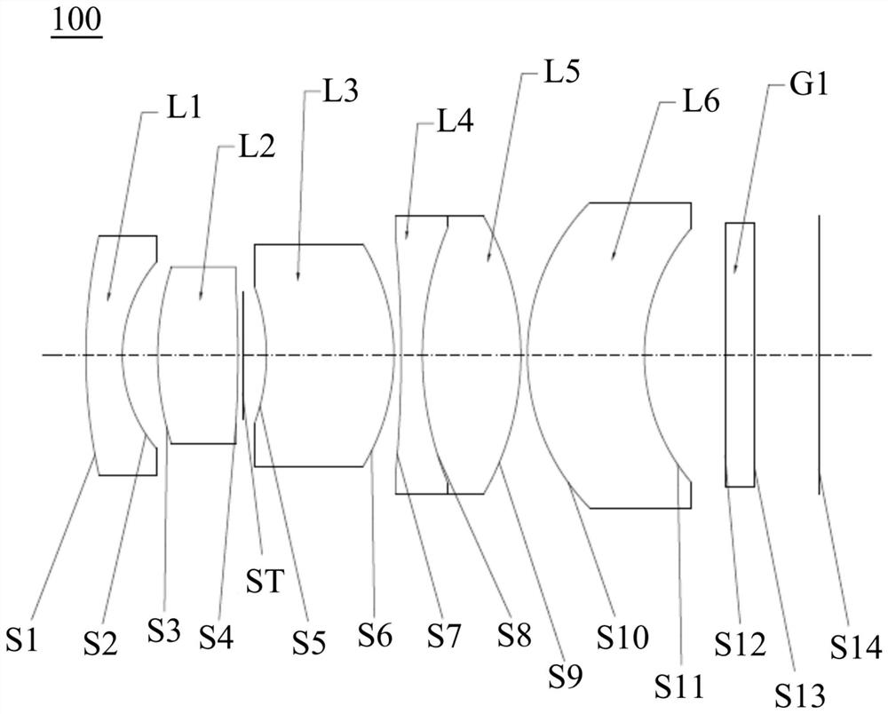
[0081] see figure 1 , a structural schematic diagram of an optical imaging lens 100 provided in the first embodiment of the present invention, which includes in sequence from the object side to the imaging surface: a first lens L1, a second lens L2, a stop ST, a third lens L3, and a fourth lens L4, fifth lens L5, sixth lens L6, filter G1.
[0082] The first lens L1 has negative refractive power, the object side S1 of the first lens is a convex surface, and the image side S2 of the first lens is a concave surface;
[0083] The second lens L2 has a positive refractive power, and both the object side S3 and the image side S4 of the second lens are convex;
[0084] The third lens L3 has positive refractive power, the object side S5 of the third lens is concave, and the image side S6 of the third lens is convex;
[0085] The fourth lens L4 has a negative refractive power, and the object side S7 and the image side of the fourth lens are concave;
[0086] The fifth lens L5 has pos...
no. 2 example
[0101] see Figure 6 , is a schematic structural diagram of the optical imaging lens 200 provided by the second embodiment. The optical imaging lens 200 among the present embodiment is roughly the same as the optical imaging lens 100 among the first embodiment, the difference is that: the image side S4 of the second lens of the optical imaging lens 200 among the present embodiment is a concave surface, and the cemented lens The fourth lens L4 in the group is a biconvex lens with positive refractive power, and the fifth lens L5 is a biconcave lens with negative refractive power, and the radius of curvature and material selection of each lens are different. The relevant parameters of each lens are shown in Table 3 shown.
[0102] table 3
[0103]
[0104]
[0105] The parameters of each lens aspheric surface in this embodiment are shown in Table 4.
[0106] Table 4
[0107] face number K B C D E F S10 -0.848113 4.7480E-04 -1.3887E-05 2.0417E-06 -...
no. 3 example
[0119] see Figure 11 , which is a schematic structural diagram of the imaging device 300 provided in the third embodiment of the present invention, the imaging device 300 includes an imaging element 310 and the optical imaging lens (such as the optical imaging lens 100 ) in any of the above embodiments. The imaging element 310 may be a CMOS (Complementary Metal Oxide Semiconductor, Complementary Metal Oxide Semiconductor) image sensor, and may also be a CCD (Charge Coupled Device, Charge Coupled Device) image sensor.
[0120] The imaging device 300 may be a vehicle monitoring device, a drone, a panoramic camera, or any other form of electronic device loaded with an optical imaging lens.
[0121] The imaging device 300 provided in this embodiment includes the optical imaging lens in any of the above embodiments. Since the optical imaging lens has the advantages of high pixels, small volume, low distortion and good thermal stability, the imaging device 300 has high pixels, It ...
PUM
 Abstract
Description
Claims
Application Information
 - R&D
- Intellectual Property
- Life Sciences
- Materials
- Tech Scout
- Unparalleled Data Quality
- Higher Quality Content
- 60% Fewer Hallucinations
Browse by: Latest US Patents, China's latest patents, Technical Efficacy Thesaurus, Application Domain, Technology Topic, Popular Technical Reports.
© 2025 PatSnap. All rights reserved.Legal|Privacy policy|Modern Slavery Act Transparency Statement|Sitemap|About US| Contact US: help@patsnap.com