
Numerical control chuck gang tool lathe for precision bearing machining

A technology of precision bearings and numerical control cards, applied in metal processing equipment, metal processing machinery parts, manufacturing tools, etc., can solve the problems of unfavorable and effective cleaning, high work intensity, and easy sticking of waste chips to the inner wall of lathes, etc. Repeated cleaning, reduced work intensity, simple operation and humanized effect

Inactive Publication Date: 2021-04-27
襄阳美金环轴承有限公司
View PDF9 Cites 1 Cited by
  • Summary
  • Abstract
  • Description
  • Claims
  • Application Information

AI Technical Summary

Problems solved by technology

[0004] In order to overcome the above-mentioned defects of the prior art, the present invention provides a CNC chuck-arranging tool lathe for precision bearing processing. The technical problem to be solved by the present invention is: when the existing lathe is in use, the waste debris generated by it needs to be Clean up to prevent the waste from affecting the normal use of the lathe, but when cleaning the waste, because the waste usually contains cutting fluid, the waste is easy to stick to the inner wall of the lathe, which is not conducive to effective cleaning. And lead to the problem of high work intensity when cleaning

Method used


Image

  • Numerical control chuck gang tool lathe for precision bearing machining
  • Numerical control chuck gang tool lathe for precision bearing machining
  • Numerical control chuck gang tool lathe for precision bearing machining

Examples


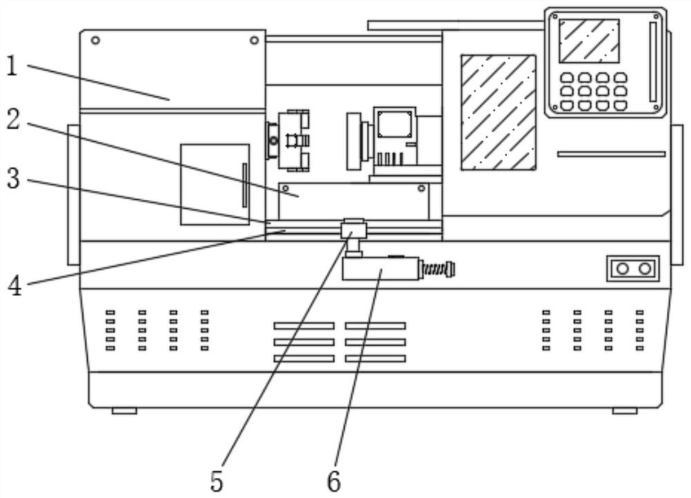
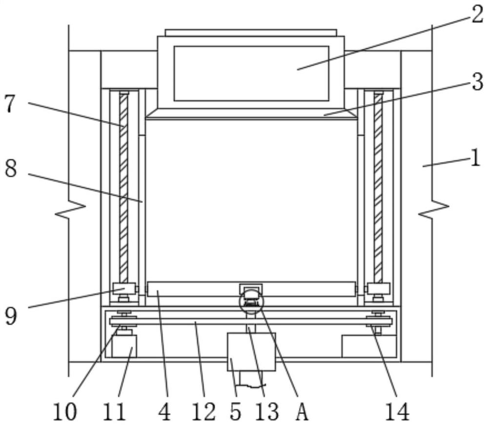
Embodiment Construction

[0027] The following will clearly and completely describe the technical solutions in the embodiments of the present invention with reference to the accompanying drawings in the embodiments of the present invention. Obviously, the described embodiments are only some, not all, embodiments of the present invention. Based on the embodiments of the present invention, all other embodiments obtained by persons of ordinary skill in the art without making creative efforts belong to the protection scope of the present invention.

[0028] Such as Figure 1-7 As shown, the present invention provides a kind of precision bearing machining CNC chuck cutter row lathe, comprising a lathe 1, a material guide device 2 is fixedly connected in the lathe 1, and a material guide plate 3 is fixedly connected to the front of the material guide device 2, through The material guide device 2 cooperates with the tilted material guide plate 3, which can facilitate the export of the waste after cleaning the...


PUM


Abstract

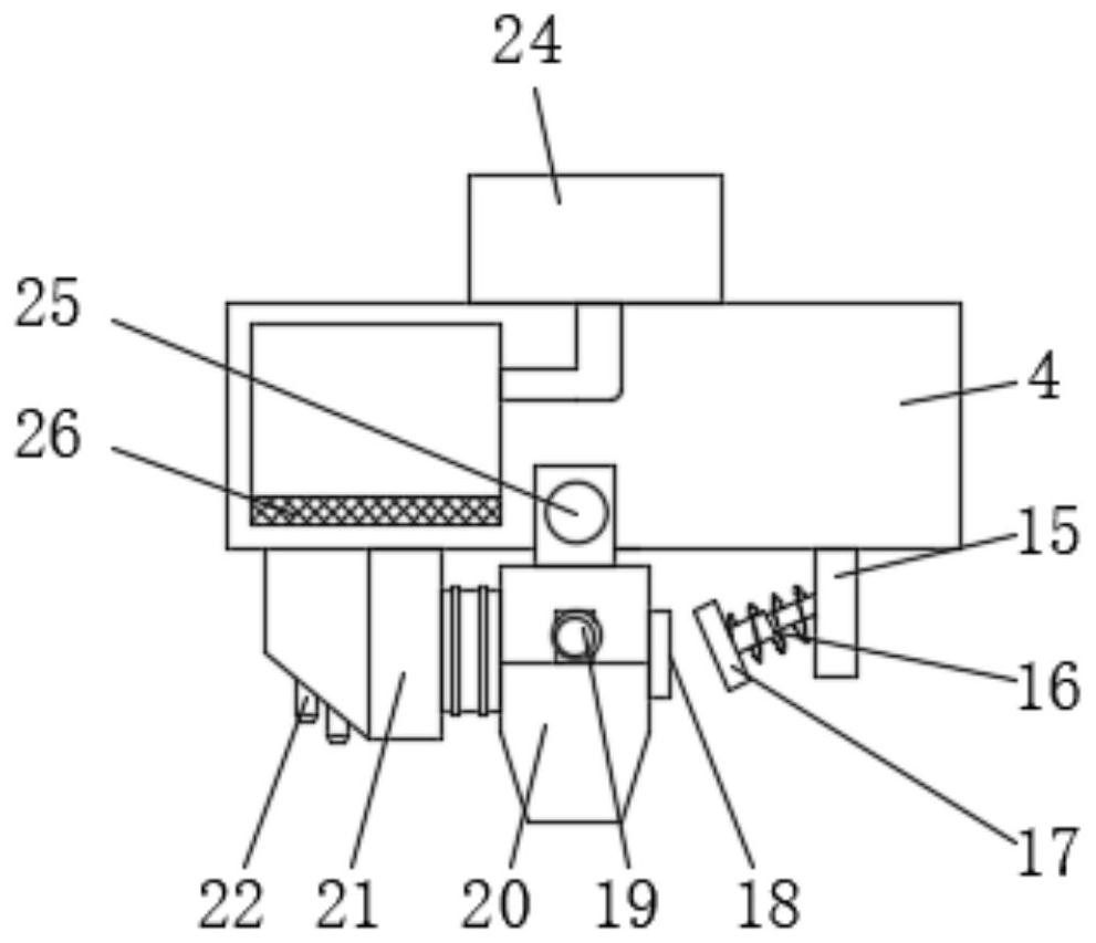
The invention discloses a numerical control chuck gang tool lathe for precision bearing machining, and particularly relates to the technical field of mechanical equipment. The numerical control chuck gang tool lathe comprises a lathe body, a material guiding device is fixedly connected to the interior of the lathe body, a material guiding plate is fixedly connected to the front face of the material guiding device, guiding grooves are formed in the left side face and the right side face of the inner wall of the lathe body, and a motor is arranged in the lathe body. According to the numerical control chuck gang tool lathe, the motor is matched with a second rotating disc and a first rotating disc, two lead screws can be driven to synchronously rotate, and then a scraping plate mechanism can be driven to automatically scrape off waste scraps; meanwhile, one side of a scraping piece can be limited through a limiting block, and excessive movement of the scraping piece is prevented; through the effect of an elastic telescopic rod and a first magnetic block, it can be guaranteed that the scraping piece rotates towards one side to a certain degree, when the scraping plate mechanism resets, secondary pollution caused by the reason that residual waste scraps are brought back can be prevented, and the waste scraps can be repeatedly cleaned; and compared with a traditional lathe, the lathe can efficiently clean the waste scraps, and the working intensity is effectively relieved.

Description

technical field [0001] The invention relates to the technical field of mechanical equipment, and more specifically, the invention relates to a numerically controlled chuck-arranging tool lathe for machining precision bearings. Background technique [0002] A lathe is a machine tool that mainly uses a turning tool to turn a rotating workpiece. Drills, reamers, reamers, taps, dies and knurling tools can also be used on lathes for corresponding processing. With the development of the times, the emergence of CNC lathes has played a greater role in the development of industry. It is more convenient and accurate to operate, and the CNC chuck row tool lathe is one of the lathes, which plays an important role in the bearing processing. [0003] When the existing lathe is in use, it is necessary to clean up the waste generated by it to prevent the waste from affecting the normal use of the lathe. However, when cleaning the waste, the waste usually contains cutting fluid, resulting i...

Claims


Application Information

Patent Timeline
Patent Type & Authority Applications(China)
IPC IPC(8): B23Q11/00
CPCB23Q11/0042
Inventor 黄光军贾淑成
Owner 襄阳美金环轴承有限公司
Learn More