Smokeless energy-saving air return furnace

A return air stove, smokeless technology, applied in household stoves/stoves, lighting and heating equipment, solid heating fuel, etc., can solve the problems of rapid heat loss of flue gas, slow ignition speed, insufficient fuel combustion, etc.

Pending Publication Date: 2021-04-27
FOSHAN CHUANGXING PRECISION SHEET METAL
View PDF1 Cites 0 Cited by
  • Summary
  • Abstract
  • Description
  • Claims
  • Application Information

AI Technical Summary

Problems solved by technology

But still there are following problems in this scheme in actual use: (1) when igniting, be to ignite by ignition rod, and the main principle of ignition rod is to heat the heating tube to high temperature by electricity, then ignite fuel, such consequence The reason is that the temperature rise of the furnace body is slow and cannot be heated in time, and there is a bigger problem that the ignition speed is slow. In this way, the temperature of the fuel is not high during the ignition process, and the combustion of the fuel is not sufficient when it is ignited, resulting in a fire in the process of ignition. More smog, and the smog will diffuse into the house through the shell gap of the return air furnace, causing discomfort to the user, but the current existing technology cannot solve this problem well; (2) the ash generated by the fuel is easy to accumulate in the furnace The furnace bridge is blocked by the bottom of the core, resulting in the problem of insufficient combustion in the furnace due to insufficient oxygen supply, resulting in large smoke pollution, low thermal efficiency, and inability to effectively use the heat in the flue gas; (3) The heat loss in the flue gas is relatively large Fast, it can't play a better heating effect, and it can't heat the countertop well, so the food placed on the countertop will cool down quickly, which is inconvenient for people to use

Method used


Image

  • Smokeless energy-saving air return furnace
  • Smokeless energy-saving air return furnace
  • Smokeless energy-saving air return furnace

Examples


Embodiment Construction

[0020] In order to make the purpose, technical solutions and advantages of the present invention more clear, the technical solutions in the embodiments of the present invention will be clearly and completely described below in conjunction with the accompanying drawings and embodiments, and in conjunction with the accompanying drawings in the embodiments of the present invention. Apparently, the described embodiments are only some of the embodiments of the present invention, not all of them. Based on the embodiments of the present invention, all other embodiments obtained by persons of ordinary skill in the art without making creative efforts belong to the protection scope of the present invention.

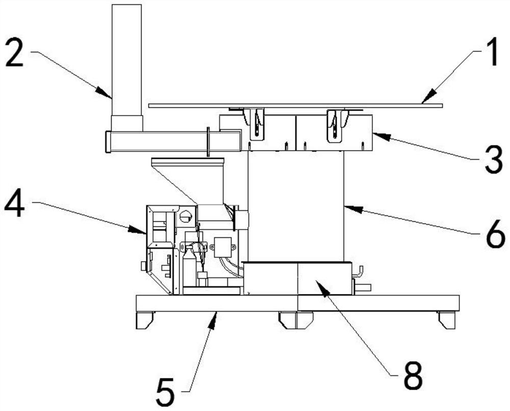
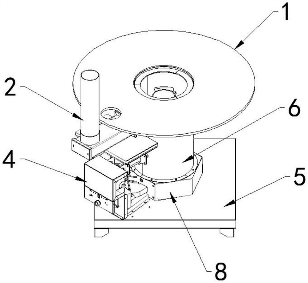
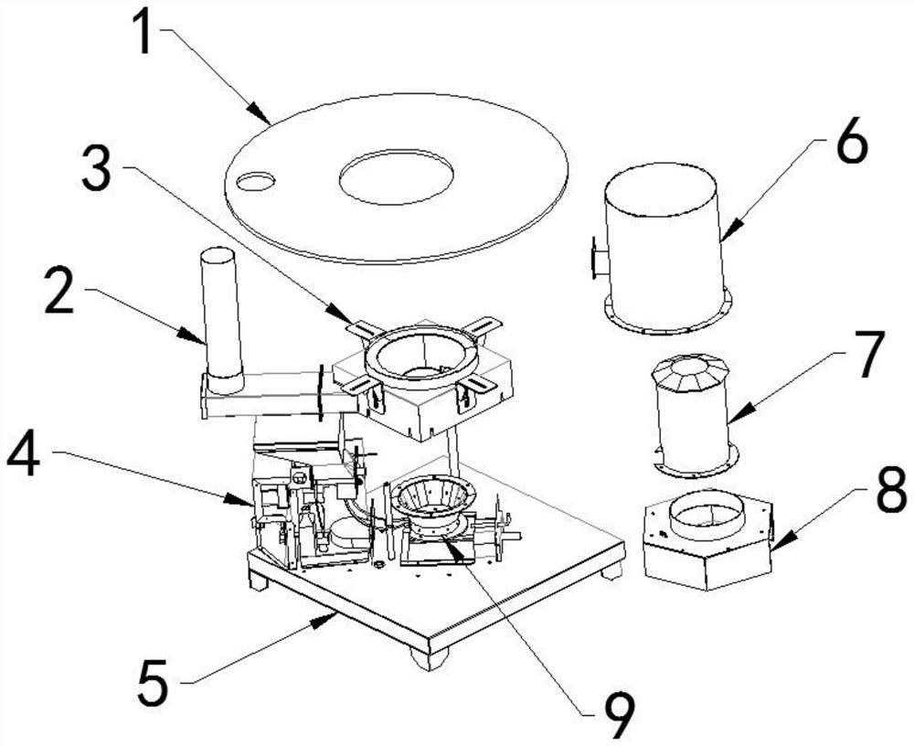
[0021] like figure 1 , image 3 , Figure 5 and Image 6 As shown, a smokeless energy-saving return air furnace includes a base 5 and a burner 4 respectively installed on the base 5, and the inside of the burner 4 is respectively equipped with a fuel storage tank 11, a driving d...


PUM


Abstract

The invention discloses a smokeless energy-saving air return furnace. The smokeless energy-saving air return furnace comprises a base and a combustor installed on the base, a fuel storage box, a driving device and a pulse igniter are installed inside the combustor, the pulse igniter is connected with a first electrode and a second electrode through a first wire and a second wire, an air bag cover is installed on one side of the combustor, a combustion chamber outer shell is installed at the top of the air bag cover, a heat insulation device is installed at the top of the combustion chamber outer shell, a combustion chamber inner shell is installed inside the combustion chamber outer shell, and a combustion chamber device is installed between the air bag cover and the combustion chamber inner shell. Before ignition, the driving device is firstly controlled to spray a certain amount of combustible liquid to solid fuel in a combustion chamber, then the pulse igniter works, the pulse igniter can control the first electrode and the second electrode to generate electric arcs, so that the combustible liquid in the combustion chamber is ignited, and the solid fuel in a combustion chamber body is quickly ignited under the combustion-supporting action of the combustible liquid, so that smoke is not generated.

Description

technical field [0001] The invention relates to the technical field of heating equipment, in particular to a smokeless energy-saving return air furnace. Background technique [0002] The air return furnace is a device that burns coal or other biomass fuels for heating or cooking. It mainly includes a furnace barrel for heat insulation, and a combustion chamber is set in the furnace body. The coal or biomass fuel is put into Heat is generated after combustion in the combustion chamber. At present, the country is actively advocating a low-carbon environment, and energy saving and consumption reduction have become the theme of the world. If the traditional stove is still used, it will not only waste resources, but also waste a lot of fuel, and the combustion firepower is not strong, the firepower cannot be adjusted, and there is a problem that it is difficult to seal the fire. lead to low combustion efficiency. And in the small and medium-sized cities and rural areas in South...

Claims


Application Information

Patent Timeline
IPC IPC(8): F24B1/16F24B13/00F24B13/04
CPCF24B1/16F24B13/00F24B13/008F24B13/04
Inventor 欧阳志尧彭凯杰陈如龙潘梓豪
Owner FOSHAN CHUANGXING PRECISION SHEET METAL
Why Eureka
Try Eureka