35kv indoor transformer substation cleaning device with dust-proof function

A technology for cleaning devices and substations, which is applied to cleaning methods using tools, switchgear, and dust removal, etc. It can solve problems that affect the health of cleaning workers, cannot clean large-scale cleaning equipment, and limited indoor space in substations. Effects of cleaning floating dust, protecting health, and improving convenience

Pending Publication Date: 2021-04-30
刘正江
View PDF10 Cites 1 Cited by
  • Summary
  • Abstract
  • Description
  • Claims
  • Application Information

AI Technical Summary

Problems solved by technology

For indoor substations, due to the limitation of space, it cannot be cleaned by large-scale cleaning equipment, which requires a specially designed small-scale cleaning structure for cleaning
However, the existing cleaning device has a very simple structure and only has a cleaning function, and because the indoor space of the substation is very limited, a large amount of floating dust will be generated during the cleaning process and permeate the substation, which not only affects the health of the cleaning staff, but also enters the substation. The interior of the equipment directly affects the service life of the equipment

Method used


Image

  • 35kv indoor transformer substation cleaning device with dust-proof function
  • 35kv indoor transformer substation cleaning device with dust-proof function
  • 35kv indoor transformer substation cleaning device with dust-proof function

Examples


Embodiment 1

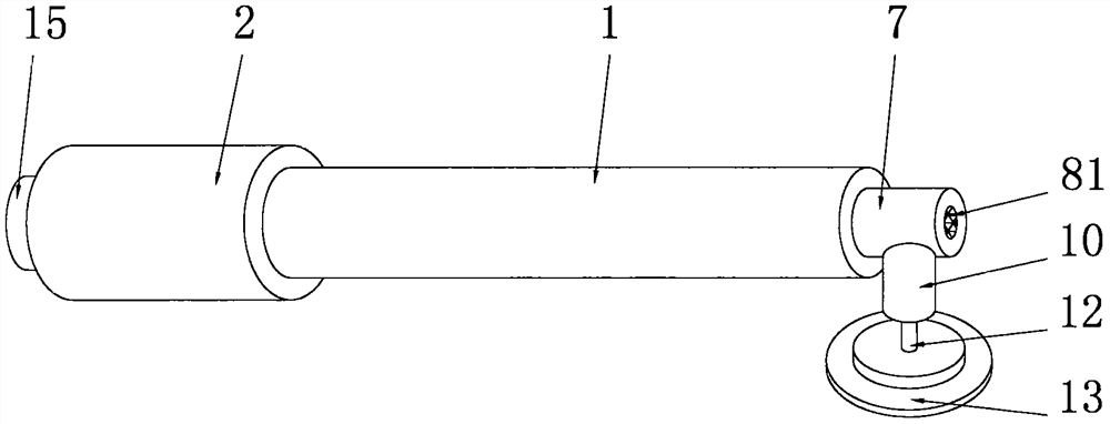
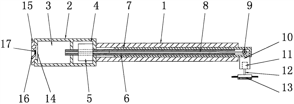
[0030] See Figure 1-2 , a 35kv indoor substation cleaning device with dustproof function, including a guide tube 1, the guide tube 1 is a round tube structure with open left and right ends, one end of the guide tube 1 is fixedly connected to the handle 2, and the guide tube 1 The axis coincides with the axis of the handle 2. The handle 2 is provided with a dust storage chamber 3 and an extension chamber 4. The extension chamber 4 is located on the right side of the dust storage chamber 3. The extension chamber 4 is provided with an extension motor 5. The guide tube 1 is provided with a screw 6, the axis of the screw 6 coincides with the axis of the guide tube 1, the screw 6 is a hollow tube structure, one end of the screw 6 extends through the motor 5 and connects the dust storage chamber 3, the screw 6 It is the rotor of the extension motor 5. The screw rod 6 is rotatably connected to the handle 2. The outer side of the screw rod 6 is provided with a shrinking tube 7 matched...

Embodiment 2

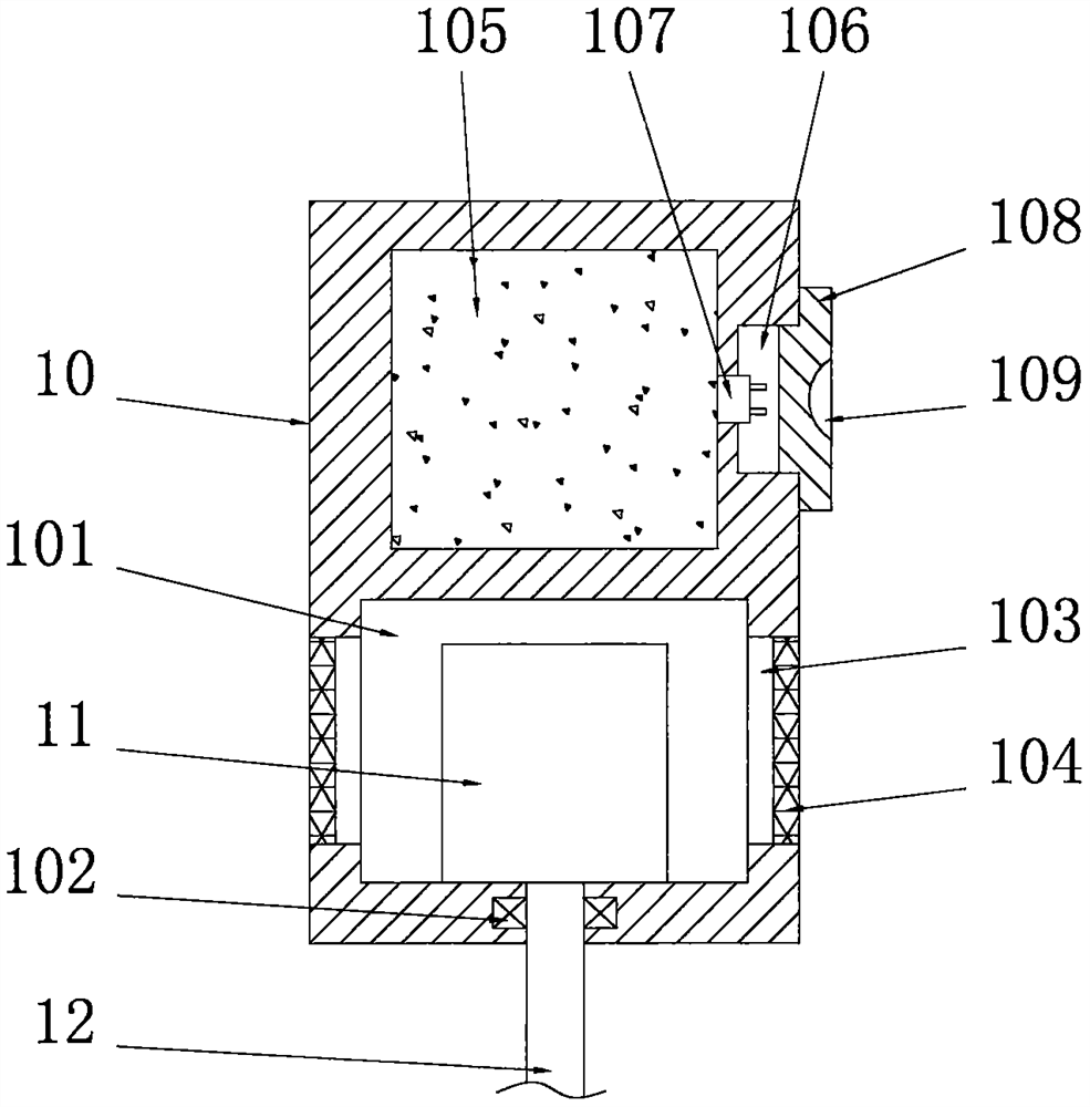
[0034] See image 3 The difference from Embodiment 1 is that the cleaning cylinder 10 is provided with a power chamber 101, the cleaning motor 11 is fixedly installed on the inner cavity bottom wall of the power chamber 101, and the rotating shaft 12 is connected to the cleaning chamber through a bearing 102 for rotation. On the cylinder 10, the side wall of the power chamber 101 is uniformly connected with a plurality of heat dissipation windows 103, and the second protective net 104 is installed in the heat dissipation window 103, and the heat dissipation of the cleaning motor 11 can be directly performed through the heat dissipation windows 103, which can effectively Guarantee the continuous operation of the cleaning motor 11;

[0035] The cleaning cylinder 10 is embedded with a storage battery 105, and the storage battery 105 is arranged above the power chamber 101. One side of the cleaning cylinder 10 is provided with a charging chamber 106, and the inner wall of the char...

Embodiment 3

[0037] See Figure 4-5 The difference from Embodiment 1 is that the cleaning assembly 13 includes a seat cover 1301, the seat cover 1301 is a disc-shaped structure, the bottom end of the rotating shaft 12 is fixedly connected to the top end of the seat cover 1301, and the axis of the rotating shaft 12 Coincident with the axis of the seat cover 1301, the bottom end of the seat cover 1301 is provided with an installation cavity 1302, the top wall of the inner cavity of the installation cavity 1302 is provided with a substrate 1303, and the edge of the seat cover 1301 is evenly provided with a number of pressing Rod 1307, the bottom end of the pressure rod 1307 runs through the base plate 1303 and is fixedly connected with a cleaning plate 1304 matched with the installation cavity 1302, the top end of the pressure rod 1307 is fixedly connected with the pressure plate 1308, and the pressure rod 1307 is respectively connected to the seat cover 1301 and the base plate 1303 Sliding c...


PUM


Abstract

The invention discloses a 35kv indoor transformer substation cleaning device with a dust-proof function. The device comprises a guide pipe, wherein one end of the guide pipe is fixedly connected to a handle; a dust storage cavity and an extension cavity are arranged in the handle; an extension motor is arranged in the extension cavity; a screw is arranged in the guide pipe; one end of the screw penetrates through the extension motor and is connected to the dust storage cavity in a penetrating mode; the screw is a rotor of the extension motor; the outer side of the screw is sleeved with a shrinkage cylinder matched with the guide pipe; the bottom end of the shrinkage cylinder is fixedly connected to a cleaning cylinder matched with the guide pipe; a cleaning motor is arranged in the cleaning cylinder; a rotating shaft is rotationally connected to the cleaning motor; and the bottom end of the rotating shaft is fixedly connected to a cleaning component. When the cleaning component works, external floating dust air is pumped through a dust suction pump, so that floating dust raised by the cleaning component enters a dust suction pipe along with the air and is injected into the dust storage cavity along the dust suction pipe and an inner cavity of the screw, the floating dust can be effectively prevented from diffusing into a transformer substation room, and the cleaning quality in the transformer substation room can be further improved.

Description

technical field [0001] The invention relates to the technical field of substation cleaning equipment, in particular to a 35kv indoor substation cleaning device with a dust-proof function. Background technique [0002] A substation is a place in a power system that transforms voltage and current, receives electric energy and distributes electric energy. The substation in the power plant is a step-up substation, whose function is to boost the electric energy generated by the generator and feed it to the high-voltage grid. [0003] The substation needs to be inspected or maintained regularly to ensure the safety of the working environment of the components of the substation. For indoor substations, due to the limitation of space, it cannot be cleaned by large-scale cleaning equipment, which requires a specially designed small-scale cleaning structure for cleaning. However, the existing cleaning device has a very simple structure and only has a cleaning function, and because t...

Claims


Application Information

Patent Timeline
Patent Type & Authority Applications(China)
IPC IPC(8): B08B15/04B08B1/04B08B1/00B08B13/00H02B3/00
CPCB08B15/04B08B1/04B08B1/007B08B13/00H02B3/00
Inventor 刘正江
Owner 刘正江
Why Eureka
Try Eureka