
Copper-aluminum different-material cooling plate friction stir tunnel forming method and cooling plate

A friction stirring and cooling plate technology, applied in non-electric welding equipment, welding equipment, metal processing equipment, etc., can solve the problems of difficult material overflow, low processing efficiency, and inadaptability to integrated equipment

Inactive Publication Date: 2021-04-30
哈工万联智能装备(苏州)有限公司
View PDF9 Cites 1 Cited by
  • Summary
  • Abstract
  • Description
  • Claims
  • Application Information

AI Technical Summary

Problems solved by technology

The cooling plate material prepared by conventional friction stir tunnel forming is usually aluminum alloy, but the heat dissipation coefficient of aluminum alloy is small, which is not conducive to efficient heat dissipation; in order to achieve better heat dissipation effect and improve heat dissipation performance, it is necessary to Or a certain shape that promotes heat dissipation is processed internally, but the production process is complicated; at the same time, the existence of tunnels will reduce the effective bearing area and thickness of the joints and parts, thereby reducing the load-bearing performance of the joints, resulting in a reduction in the bearing capacity of the parts, requiring additional boards Thickness is used to ensure that the cooling plate obtains a certain strength, which is not suitable for the needs of integrated equipment; in addition, it is difficult for conventional aluminum alloy welding materials to overflow the weld surface smoothly, the material overflow is difficult, and the processing efficiency is low

Method used


Image

  • Copper-aluminum different-material cooling plate friction stir tunnel forming method and cooling plate
  • Copper-aluminum different-material cooling plate friction stir tunnel forming method and cooling plate

Examples


Embodiment Construction

[0032] In order to explain the overall concept of the present invention more clearly, the following will be described in detail by way of examples in conjunction with the accompanying drawings.

[0033] In describing the present invention, it is to be understood that the terms "center", "upper", "lower", "front", "rear", "left", "right", "vertical", "horizontal", The orientation or positional relationship indicated by "top", "bottom", "inner", "outer", "axial", "radial" and "circumferential" are based on the orientation or positional relationship shown in the drawings, only It is for the convenience of describing the present invention and simplifying the description, but does not indicate or imply that the referred device or element must have a specific orientation, be constructed and operated in a specific orientation, and thus should not be construed as limiting the present invention.

[0034]In addition, the terms "first" and "second" are used for descriptive purposes only,...


PUM


Abstract

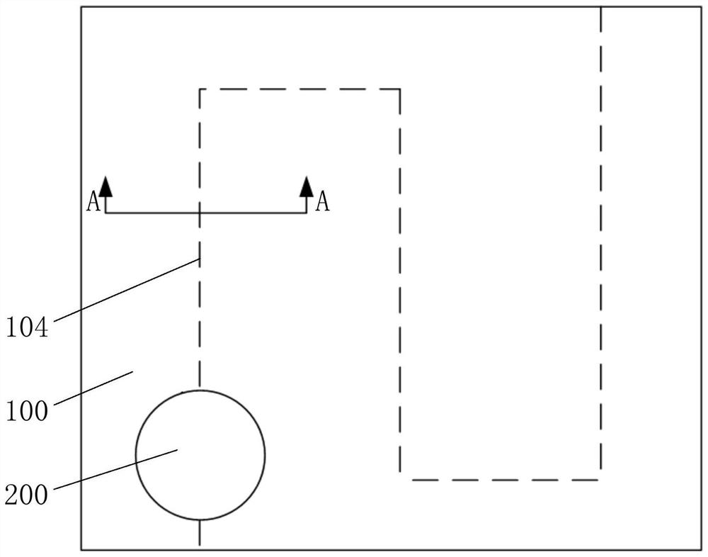
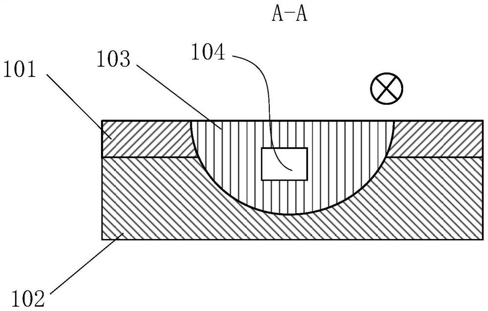
The invention discloses a copper-aluminum different-material cooling plate friction stir tunnel forming method and a cooling plate. The copper-aluminum different-material cooling plate friction stir tunnel forming method comprises the following steps of selecting a copper alloy plate and an aluminum alloy plate as base materials, and removing oxide layers on the surfaces of the copper alloy plate and the aluminum alloy plate; stacking, clamping and fixing the copper alloy plate and the aluminum alloy plate, taking the copper alloy plate as an upper copper plate of the cooling plate, and taking the aluminum alloy plate as a lower aluminum plate of the cooling plate; starting a main shaft of friction stir welding equipment to drive a stirring head to rotate, so that the stirring head is inserted into the upper copper plate and the lower aluminum plate by a preset depth, and the stirring head keeps rotating; driving the stirring head to horizontally move along a designated welding path to weld the upper copper plate and the lower aluminum plate, so that the cooling plate is obtained; and meanwhile, enabling the stirring head to rotate to enable materials in a weld joint to flow upwards, overflow and deposit on the surface of the weld joint, so that a tunnel is formed in the cooling plate.

Description

technical field [0001] The invention relates to a manufacturing method of a cooling plate and the cooling plate, in particular to a forming method of a copper-aluminum heterogeneous material cooling plate and a friction stirring tunnel forming method and the cooling plate. Background technique [0002] Compared with the conventional air cooling technology, the medium cooling technology has the characteristics of strong heat dissipation and high heat conversion efficiency, and has a strong application prospect in products that require large-area heat dissipation. It has been widely used in battery packs, engines, and baking boxes. Cooling in other aspects, but medium cooling requires a channel for conveying the medium. [0003] At present, the cooling medium is hydraulically conveyed by hoses on the aircraft to cool under the wing surface. However, the fixing of cooling hoses requires complicated wiring and additional auxiliary fixing devices, which is not conducive to simpli...

Claims


Application Information

Patent Timeline
IPC IPC(8): B23K20/12B23K20/22
CPCB23K20/127B23K20/22
Inventor 万龙刘景麟黄体方
Owner 哈工万联智能装备(苏州)有限公司
Learn More