Permanent magnet synchronous motor cogging torque test method and device
A permanent magnet synchronous motor, cogging torque technology, used in motor generator testing, measuring devices, force/torque/work measuring instruments, etc.
- Summary
- Abstract
- Description
- Claims
- Application Information
AI Technical Summary
Problems solved by technology
Method used
Image
Examples
Embodiment 1
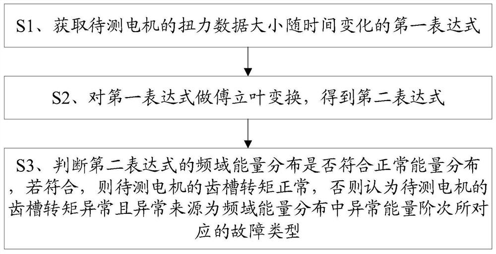
[0058] Please refer to figure 1 , Figure 4 to Figure 6 , Embodiment one of the present invention is:
[0059] A method for testing the cogging torque of a permanent magnet synchronous motor, comprising the steps of:
[0060] S1. Acquiring the first expression of the torque data of the motor 1 to be tested varying with time;
[0061] S2. Perform Fourier transform on the first expression to obtain the second expression;
[0062] S3. Judging whether the frequency-domain energy distribution of the second expression conforms to the normal energy distribution, if so, the cogging torque of the motor 1 to be tested is normal, otherwise the cogging torque of the motor 1 to be tested is considered to be abnormal and the source of the abnormality is the fault type corresponding to the abnormal energy order in the frequency domain energy distribution. In this embodiment, according to whether the energy distribution on the preset order of the second expression conforms to the preset e...
Embodiment 2
[0084] Please refer to 1 and Figure 4 , the second embodiment of the present invention is:
[0085] A method for testing the cogging torque of a permanent magnet synchronous motor, on the basis of the above implementation example, after step S3, also includes:
[0086] S4. Perform an inverse Fourier transform on the second expression to obtain a third expression;
[0087] S5. Obtain the maximum torque value, the minimum torque value and the average torque value of the motor 1 to be tested from the torque value distribution in the third expression within the preset time;
[0088] S6. Subtracting the maximum value of the torque from the minimum value of the torque to obtain the value of the cogging torque.
[0089] In this example, the corresponding Figure 4 As shown, the second expression is inversely transformed by Fourier to obtain the third expression representing the change of the torque data with time, so that the average value of the torque and the value of the coggi...
Embodiment 3
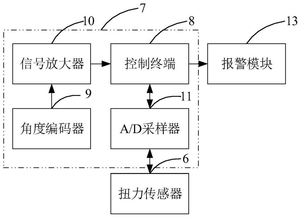
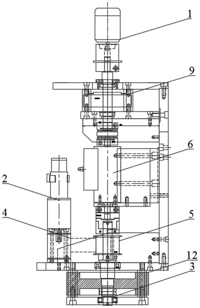
[0094] Please refer to Figure 2 to Figure 3 , Embodiment three of the present invention is:
[0095] A permanent magnet synchronous motor cogging torque test device, such as figure 2 and image 3 As shown, it includes a motor to be tested 1, a drive motor 2, a rotating shaft 3, a belt 4, a pulley 5, a torque sensor 6 and a main control module 7; wherein, the rotor of the motor to be tested 1 is fixedly connected to one end of the rotating shaft 3, and the pulley 5 and The torque sensors 6 are respectively socketed on the rotating shaft 3 , one end of the belt 4 is socketed on the pulley 5 , and the other end is socketed on the rotating shaft of the drive motor 2 , and the main control module 7 is electrically connected to the torque sensor 6 . The main control module 7 is used to execute all the steps of the method for testing the cogging torque of a permanent magnet synchronous motor in the first or second embodiment.
[0096] In this embodiment, combined with the above ...
PUM
 Abstract
Description
Claims
Application Information
 - R&D
- Intellectual Property
- Life Sciences
- Materials
- Tech Scout
- Unparalleled Data Quality
- Higher Quality Content
- 60% Fewer Hallucinations
Browse by: Latest US Patents, China's latest patents, Technical Efficacy Thesaurus, Application Domain, Technology Topic, Popular Technical Reports.
© 2025 PatSnap. All rights reserved.Legal|Privacy policy|Modern Slavery Act Transparency Statement|Sitemap|About US| Contact US: help@patsnap.com


