
Multifunctional cable testing system and using method thereof

A cable testing, multi-functional technology, used in continuity testing, dielectric strength testing, components of electrical measuring instruments, etc., can solve the problems of inconvenient movement, single function, low impact energy, etc., and achieve convenient movement and installation. The effect of fixing, reducing the possibility of damage, and facilitating movement and transportation

Pending Publication Date: 2021-04-30
CHINA PETROLEUM & CHEM CORP +1
View PDF0 Cites 0 Cited by
  • Summary
  • Abstract
  • Description
  • Claims
  • Application Information

AI Technical Summary

Problems solved by technology

[0003] The capacitance capacity of the traditional high-voltage shock generator is fixed, and the output shock energy is sufficient when testing cables with high voltage levels, but when testing low-voltage cables, the output voltage of the high-voltage shock generator cannot be too high, so using high-voltage shock generators The impact energy output by the generator is too small, and the cable fault point is not easy to break down, which makes it difficult to test the low-voltage cable fault, so it is necessary to purchase a special voltage shock generator for low-voltage cable testing.
Sometimes it is very inconvenient to carry two kinds of voltage shock signal generators during on-site testing. The existing cable fault tester has a single function and is very inconvenient to move. Therefore, a set of multi-functional cable testing system is formed, which is convenient for users to use on site.

Method used


Image

  • Multifunctional cable testing system and using method thereof
  • Multifunctional cable testing system and using method thereof
  • Multifunctional cable testing system and using method thereof

Examples


Embodiment Construction

[0032] In order to make the object, technical solution and advantages of the present invention clearer, the present invention will be further described in detail below in conjunction with the accompanying drawings and embodiments. It should be understood that the specific embodiments described here are only used to explain the present invention, not to limit the present invention.

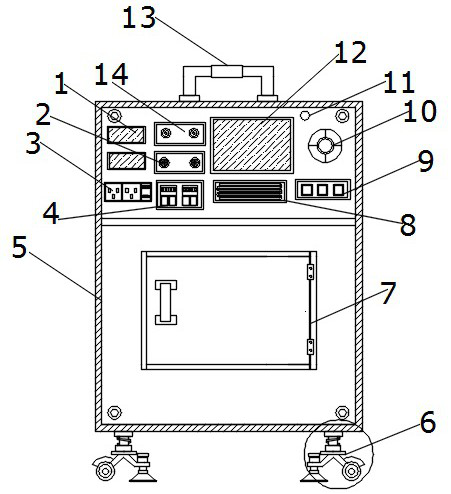
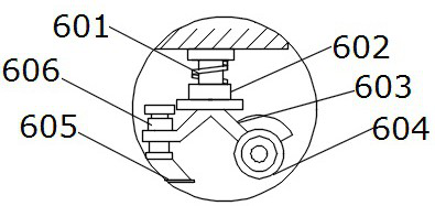
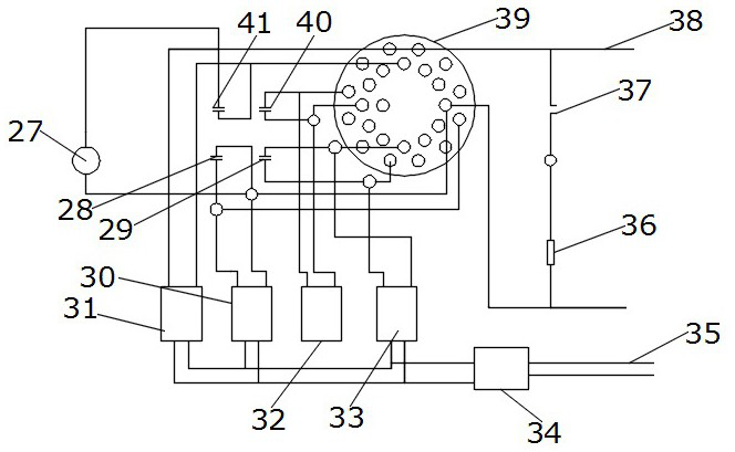
[0033] refer to Figure 1-5 , a multifunctional cable testing system, including a shock-absorbing mobile-fixed integrated mechanism 6, the upper end of the shock-absorbed mobile-fixed integrated mechanism 6 is fixedly installed on the outer wall of the bottom end of the cable test box 5, and a power distribution device is arranged outside the lower end of the cable test box 5 Box 7, a handle 13 is fixedly installed on the top of the cable test box body 5, a signal light 11 is arranged on the left side of the upper end of the cable test box body 5, and a function selection button 10 is arranged on t...


PUM


Abstract

The invention discloses a multifunctional cable testing system and a using method thereof. The multifunctional cable testing system comprises a damping, moving and fixing integrated mechanism, the upper end of the damping, moving and fixing integrated mechanism is fixedly installed on the outer wall of the bottom end of a cable testing box body, and a distribution box is arranged on the outer side of the lower end of the cable testing box body; a handle is fixedly installed at the top end of the cable test box body, a signal lamp is arranged outside the left side of the upper end of the cable test box body, a function selection button is arranged at the outer end of the cable test box body on the lower side of the signal lamp, and a switch button is arranged at the outer end of the cable test box body on the lower side of the function selection button; and the left side of the switch button is provided with a storage box, the left end of the storage box is provided with a pulse input interface, and the upper end of the pulse input interface is provided with a regulation and control knob. The device is provided with a high-voltage impact generator with a variable capacitance and an adjustable output voltage for cable fault testing, and is suitable for power cable fault testing of different voltage classes, and meanwhile, moving and carrying are convenient.

Description

technical field [0001] The invention belongs to the technical field of cable testing, and specifically relates to a multifunctional cable testing system and a using method thereof. Background technique [0002] In power equipment, the smoothness of wired communication and the transmission of power depend on the normal operation of cable lines. Once the line is blocked, it will cause interruption of communication and power. If the fault cannot be detected in time and eliminated quickly, it will cause great economic losses and adverse social impact. Therefore, the cable fault tester is an important tool for maintaining all kinds of cables. The cable fault tester is a set of comprehensive cable fault detection equipment, which is used for testing the open circuit, short circuit, grounding, low resistance, high resistance flashover and high resistance leakage faults of power cables as well as coaxial communication cables and local telephone cables. Accurate testing of open cir...

Claims


Application Information

Patent Timeline
IPC IPC(8): G01R31/08G01R31/58G01R31/54G01R31/12G01R1/14G01R1/04G01R1/02
CPCG01R1/02G01R1/04G01R1/14G01R31/083G01R31/1272G01R31/54G01R31/58
Inventor 刘玉林尚长泉张维进孙黎新陈志峰刘国忠牛楷文马广俊马云龙王涛
Owner CHINA PETROLEUM & CHEM CORP
Learn More