
Low-stress crystal growth method

A growth method and technology of crystal growth, applied in the direction of crystal growth, single crystal growth, single crystal growth, etc., can solve the problems of insignificant heat preservation and heating effect, thermal field influence, reduction and other problems

Active Publication Date: 2021-05-04
THE 13TH RES INST OF CHINA ELECTRONICS TECH GRP CORP
View PDF9 Cites 13 Cited by
  • Summary
  • Abstract
  • Description
  • Claims
  • Application Information

AI Technical Summary

Problems solved by technology

This kind of device uses an external moving coil to heat the crucible and the rear heating cylinder at the same time. There is power interference between the two, and the control accuracy is not high.
Crystal growth requires high temperature stability in the crucible, and the movement of the coil of the heating crucible will have a greater impact on the thermal field. Moreover, the heating cylinder is induced at the same time to shunt the coil power, which is easy to cause melt Temperature gradient fluctuates widely, leading to failure of crystal growth
Moreover, the relative position of the insulation cylinder and the crystal is far away, and the rear heating cylinder will heat the entire environment, which will reduce the entire environment, including the temperature gradient in the melt, and will also cause crystal growth to have low stability.
Moreover, the coil device heats the melt and the crystal during the cooling process at the end of crystal growth, but has no obvious effect on the heat preservation and heating of the crystal during crystal growth.
It has no obvious improvement effect on the stress and dislocation defects caused by the temperature difference between the upper and lower ends of the crystal during the crystal growth process

Method used


Image

  • Low-stress crystal growth method
  • Low-stress crystal growth method
  • Low-stress crystal growth method

Examples


Embodiment Construction

[0027] The present invention will be further described below in conjunction with the accompanying drawings.

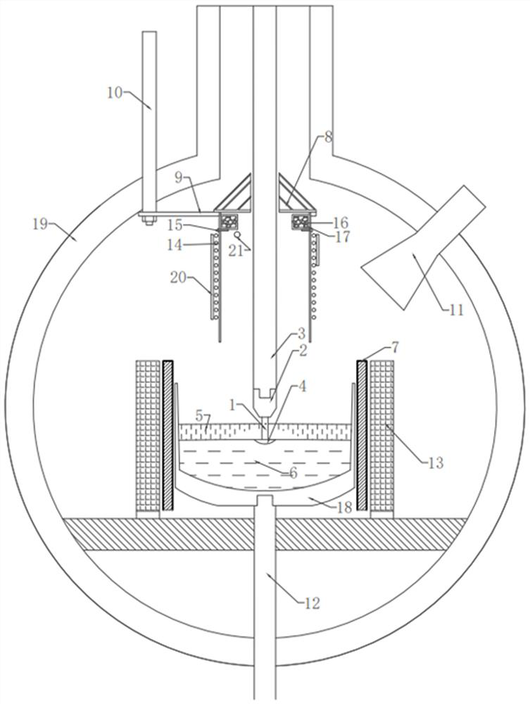
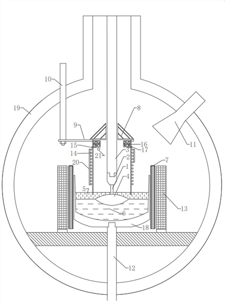
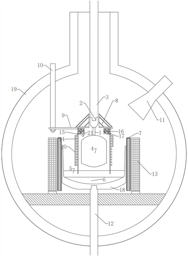
[0028] Pull method crystal growth apparatus with movable crystal heating mantle, see figure 1 , including a furnace body 19, a crucible 18 placed at the bottom of the furnace body 19 and a heating and heat preservation system, a crystal pulling mechanism facing the center of the crucible, and a quartz observation window 11 placed on the side of the furnace body 19.

[0029] The heating and heat preservation system includes a heater 7 placed around the crucible 18, a crucible rod 12 supporting the crucible 18 below, and an insulation cover 13 outside the heater 7.

[0030] The crystal pulling mechanism includes a seed rod 3 and a seed chuck 2 .

[0031] The device also includes a movable crystal heating cover, including a heating cover body 8 , a heating cover support member 9 , heating wires 14 arranged around the heating cover body 8 , and a heating cover lifting mec...


PUM


Abstract

The invention discloses a low-stress crystal growth method, and relates to the field of crystal preparation, in particular to a method for preparing low-stress and low-defect crystals by using a Czochralski method, the method is realized by using a Czochralski method crystal growth device with a movable crystal heating cover, and the crystal growth device comprises a furnace body, a crucible at the bottom of the furnace body, a heating and heat preservation system, a crystal lifting mechanism, and a quartz observation window. The device further comprises a movable crystal heating cover which comprises a heating cover body, heating wires arranged on the periphery of the heating cover body and a heating cover lifting mechanism. In the crystal growth process and after the crystal is pulled out of the melt, the movable crystal heating cover is used for covering. By adopting the method, the temperature gradient in the crystal in the crystal growth process and the cooling process after the crystal is lifted can be reduced, so that the crystal stress is reduced, the defects are reduced, the crystal cracking is avoided, the temperature gradient in the melt is kept, the stability of the crystal growth process is ensured, and the crystal yield is ensured.

Description

technical field [0001] The invention relates to the field of crystal preparation, in particular to a method for preparing low-stress and low-defect crystals by using a pulling method. Background technique [0002] The pulling method is a method of growing crystals from a melt. It is a common growth method for semiconductor crystals and optical crystals. This method has the characteristics of high yield, fast growth speed, and easy observation. [0003] The pulling method is commonly used as a growth method with a single heater. The pulling method is because the crystal is pulled out of the melt, especially when it is pulled to a higher position, the part of the crystal that is pulled out first will be cooled to a lower temperature due to the lower ambient temperature. However, the temperature at the solid-liquid interface of crystal growth is always maintained near the melting point of the crystal. Therefore, assuming that the longitudinal temperature distribution in the cr...

Claims


Application Information

Patent Timeline
IPC IPC(8): C30B15/00C30B15/20C30B29/42
CPCC30B15/00C30B15/203C30B29/42
Inventor 史艳磊孙聂枫王书杰付莉杰邵会民赵红飞李亚旗刘惠生孙同年康永张晓丹张鑫姜剑李晓岚王阳薛静
Owner THE 13TH RES INST OF CHINA ELECTRONICS TECH GRP CORP
Learn More