Phased array antenna with high radiation efficiency and low scattering characteristic

A phased array antenna, low-scattering technology, applied in the direction of antenna, antenna grounding device, radiating element structure, etc., can solve the problems of low system efficiency, deteriorated standing wave, low gain, etc., so as not to reduce radiation efficiency, increase The effect of isolation

Active Publication Date: 2021-05-04
UNIV OF ELECTRONICS SCI & TECH OF CHINA
View PDF4 Cites 3 Cited by
  • Summary
  • Abstract
  • Description
  • Claims
  • Application Information

AI Technical Summary

Problems solved by technology

In the document "Finite Antenna Arrays and FSS", it is proposed that by changing the antenna load, the antenna reflection wave and the resulting mode item scattering field are adjusted, so that the mode item and the structure item scattering field are offset in the incoming wave direction, and the in-band single However, on the one hand, the loads that can be used in engineering are all frequency-invariant real impedances (commonly 50Ω), and the optimal load impedances required by different frequency points are different, so this method is only applicable to single frequency points or Narrowband RCS reduction, on the other hand, this method often means worse standing wave and the resulting low gain and low system efficiency

Method used


Image

  • Phased array antenna with high radiation efficiency and low scattering characteristic
  • Phased array antenna with high radiation efficiency and low scattering characteristic
  • Phased array antenna with high radiation efficiency and low scattering characteristic

Examples


Embodiment 1

[0019] Embodiment 1: Low scattering E-plane phased array antenna unit

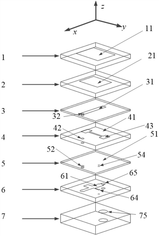
[0020] The antenna unit structure in this embodiment is shown in figure 1 , unit size 16×16mm 2 (respectively in the x and y directions), the working frequency is 8-10GHz, and the antenna is divided into four layers from top to bottom, which are: radiation patch layer, coupling feed layer, matching circuit layer, and metal floor; the antenna has a total of six layers of PCB Board, its material is Rogers 5880, the dielectric constant is 2.2, the thickness of the first to sixth PCB boards (1 to 6) are: 1.5mm, 1.5mm, 0.5mm, 1.5mm, 0.5mm, 1.5mm; metal floor The thickness is 13mm.

[0021] The radiation patch layer includes: a first radiation patch 11 , a first PCB board 1 , a second radiation patch 21 , and a second PCB board 2 . The first radiating patch 11 is a rectangular patch and is arranged at the center of the upper surface of the first PCB 1 ; the second radiating patch 21 is a rectangular patch and...

Embodiment 2

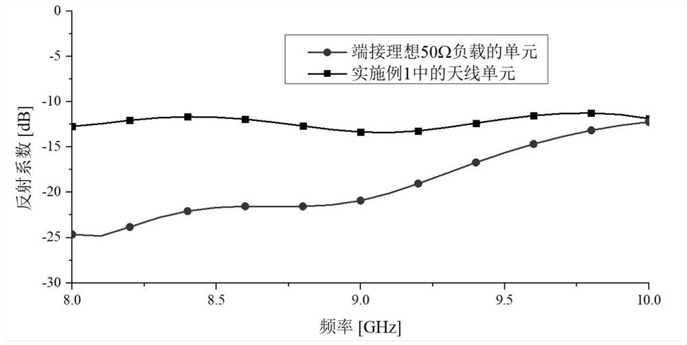
[0026] Such as image 3 In order to directly use the 50Ω ideal port feed and the standing wave of the phased array antenna unit in this embodiment, it can be seen that the standing wave deteriorates after loading the designed matching circuit, but the in-band is below -10dB and can work well; Such as Figure 4 For the single-station RCS of the two in the normal direction, it can be seen that the single-station RCS of the antenna unit in this embodiment is reduced by more than 7dB compared with the antenna unit fed by a 50Ω ideal port in most frequency bands in the band, and compared with the antenna unit of the same size The typical value of ground scattering is more than 15dB lower; therefore, the antenna unit achieves significant in-band normal single-site RCS reduction while maintaining good standing wave and radiation efficiency. Example 2: Low scattering 1×32E planar phased array antenna

[0027] In this embodiment, the antenna units in Embodiment 1 are used to form a 1...


PUM


Abstract

The invention discloses a patch phased-array antenna with high radiation efficiency and low scattering characteristics, and belongs to the technical field of antenna engineering and the technical field of radar stealth. According to the invention, the bandwidth of the antenna is increased by adopting the laminated patches; the isolation between the circuit and the antenna is increased through different layers of feed patches, matching circuits and grounding plates arranged therebetween, so that the circuit and the antenna can be independently designed; an optimal load impedance curve for realizing zero back scattering in a band is solved from the scattering mechanism of the phased-array antenna, and finally fitting design of a corresponding matching circuit is performed, so that the RCS of a single station in the band of the antenna is remarkably reduced. In the unit selection and design, an antenna unit with low structural item scattering is selected, or proper structural item scattering reduction is carried out, so that the broadband reduction of the single-station RCS can be realized on the premise of ensuring that the antenna does not deteriorate the standing wave and does not reduce the radiation efficiency.

Description

technical field [0001] The invention belongs to the technical field of antenna engineering and the technical field of radar stealth, and relates to a phased array antenna with high radiation efficiency and low backscattering. Background technique [0002] Aircraft stealth is an important topic of modern electronic warfare, and the phased array antenna in the airborne radar will produce strong scattering, which has become the biggest obstacle to further improve the stealth performance of the aircraft, so the RCS (radar cross section) of the phased array antenna is reduced very important. The current mainstream antenna RCS reduction methods are as follows: [0003] First, load the material or metamaterial. For example, in the literature "Development of a Low Radar CrossSection Antenna With Band-Notched Absorber", a radar absorbing metamaterial is proposed, which absorbs the scattered energy through the material. This method is usually accompanied by the loss of antenna gain ...

Claims


Application Information

Patent Timeline
Patent Type & Authority Applications(China)
IPC IPC(8): H01Q1/38H01Q1/48H01Q1/50H01Q23/00
CPCH01Q1/38H01Q1/48H01Q1/50H01Q23/00
Inventor 李鹏发屈世伟李小秋周志鹏孙红兵
Owner UNIV OF ELECTRONICS SCI & TECH OF CHINA
Why Eureka
Try Eureka