Adapter

An adapter and connector technology, which is applied in the directions of instruments, connections, and components of connecting devices, can solve problems such as increased cost and inability to test the electrical performance of adapters.

Pending Publication Date: 2021-05-04
ROSENBERGER ASIA PACIFIC ELECTRONIC CO LTD
View PDF0 Cites 5 Cited by
  • Summary
  • Abstract
  • Description
  • Claims
  • Application Information

AI Technical Summary

Problems solved by technology

However, in addition to the above-mentioned disadvantages, the electrical performance test by adding an adapter also has the following disadvantages: (1) For cables of different types, different adapters need to be provided for adaptation, which is likely to increase the cost; (2) ) When performing electrical performance tests on coaxial cables or single-ended coaxial cable assemblies, standard interface adapters cannot be used for electrical performance tests

Method used


Image

  • Adapter
  • Adapter
  • Adapter

Examples


Embodiment 1

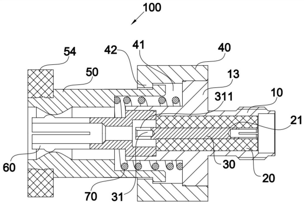
[0056] Such as Figure 5 As shown, a single-ended cable assembly consists of a cable and a connector attached to one end of the cable. Before mating the single-ended cable assembly with the adapter 100, it is necessary to process the butt end of the cable, that is, the end not connected to the connector, so that the cable core a, the cable outer conductor c, and the cable outer conductor c Insulation medium b between cable core wire a. When connecting the adapter 100, press the pressing part 54 on the outside of the locking part 50 to move the locking part 50 in the axial direction, the locking part 50 squeezes the elastic part 70, and the elastic part 70 is compressed. 55 no longer acts on the resisting portion 615 of the plurality of elastic clamping portions 612, and the plurality of elastic clamping portions 612 are in a state of expansion; further inserting the cable, during the insertion of the cable into the adapter 100, the cable core wire a passes through Insert the...

Embodiment 2

[0058] Such as Figure 6 As shown, after the two ends of the cable are processed, the cable core wire a, the cable outer conductor c and the insulating medium b between the cable outer conductor and the cable core wire appear. After processing, the process of connecting the cable to the adapter 100 is detailed in Embodiment 1, and will not be repeated here. For some larger cables, such as 141 cables, 250 cables, or 1 / 2 feeders, etc., it is only necessary to adjust the size of the inner conductor 30 and the elastic clamping piece 60 of the adapter to suit the above cables. The structure and working principle of the adapter remain unchanged.

Embodiment 3

[0060] combine Figure 8 and Figure 9 As shown, the cable assembly with parts at the tail includes a cable, a first part and a second part d, wherein the tail of the cable is provided with the second part d, and the outer diameter of the second part d is larger than the outer diameter of the cable The outer diameter of the conductor c, the second part d is a conductor, which can be installed at the tail of the cable by welding. Before the adapter 100 is connected, the inner conductor 30 and the elastic clip 60 in the adapter 100 are replaced, and the elastic clip 60 is replaced with an elastic clip with a receiving space. When connecting the adapter 100, press the pressing part 54 on the outside of the locking part 50 to move the locking part 50 in the axial direction. No longer acting on the multiple elastic clamping parts 612, the multiple elastic clamping parts 612 are in a state of expansion; further inserting the cable assembly with parts, during the insertion of the c...


PUM


Abstract

The invention discloses an adapter, which comprises a connector main body, a shell, an elastic piece, a locking piece and an elastic clamping piece, wherein the connector main body comprises an outer conductor, an inner conductor and an insulator, the shell sleeves the connector main body, a limiting space is formed between the shell and the connector main body, one end of the locking piece is movably limited in the limiting space, the other end of the locking piece is provided with an extrusion part, the elastic piece is at least partially located in the limiting space, one end of the elastic piece abuts against the side wall of the limiting space, the other end of the elastic piece abuts against the locking piece, one end of the elastic clamping piece is detachably connected with the outer conductor, the other end of the elastic clamping piece is provided with at least two elastic clamping parts, each elastic clamping part is provided with a resisting part, and the extrusion part is matched with the resisting parts so that the at least two elastic clamping parts can be gathered towards the center. The adapter can be quickly connected with a tested cable or a cable assembly, avoids damage to the cable or the cable assembly, improves the assembly efficiency, and is suitable for cables and cable assemblies of different models.

Description

technical field [0001] The invention relates to the technical field of cable testing, in particular to an adapter for testing electrical properties of cables and cable components. Background technique [0002] Cables are essential items in daily life, and they can be used for signal transmission, power transmission, etc., and are widely used. In some application scenarios, it is necessary to set corresponding parts on the cable, such as connectors, to form a cable assembly. The cable assembly includes a single-head cable assembly and a double-head cable assembly. A double-headed cable assembly means that the two ends of the cable are equipped with corresponding connectors. When cables and cable assemblies are used for signal transmission, there are certain requirements for their physical characteristics and electrical performance. During use, various tests need to be carried out on them to check whether their electrical properties are normal and meet the requirements of use...

Claims


Application Information

Patent Timeline
Patent Type & Authority Applications(China)
IPC IPC(8): H01R31/06H01R27/00H01R13/639H01R13/627H01R13/502G01R1/04G01R31/58
CPCH01R31/06H01R27/00H01R13/639H01R13/627H01R13/502G01R1/0416G01R31/58
Inventor 闫昊屠永梅刘菲
Owner ROSENBERGER ASIA PACIFIC ELECTRONIC CO LTD
Why Eureka
Try Eureka