Machine tool for producing parts of flat seaming machine
A technology of parts and interlock sewing machines, which is applied in the field of machine tools for the production of interlock sewing machine parts, can solve problems such as unfavorable production, and achieve the effects of convenient processing, convenient cutting and convenient clamping
- Summary
- Abstract
- Description
- Claims
- Application Information
AI Technical Summary
Problems solved by technology
Method used
Image

Examples
Embodiment Construction
[0022] The following will clearly and completely describe the technical solutions in the embodiments of the present invention with reference to the accompanying drawings in the embodiments of the present invention. Obviously, the described embodiments are only some, not all, embodiments of the present invention. Based on the embodiments of the present invention, all other embodiments obtained by persons of ordinary skill in the art without making creative efforts belong to the protection scope of the present invention.
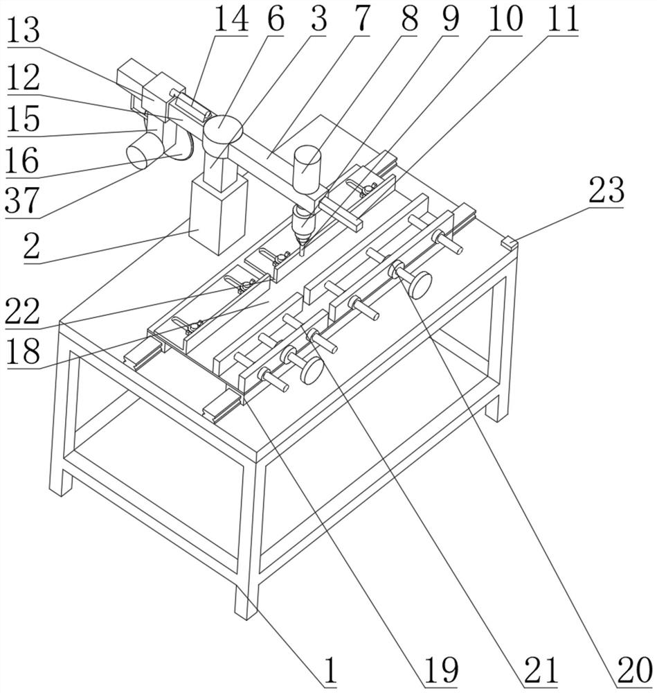
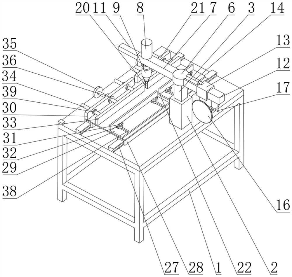
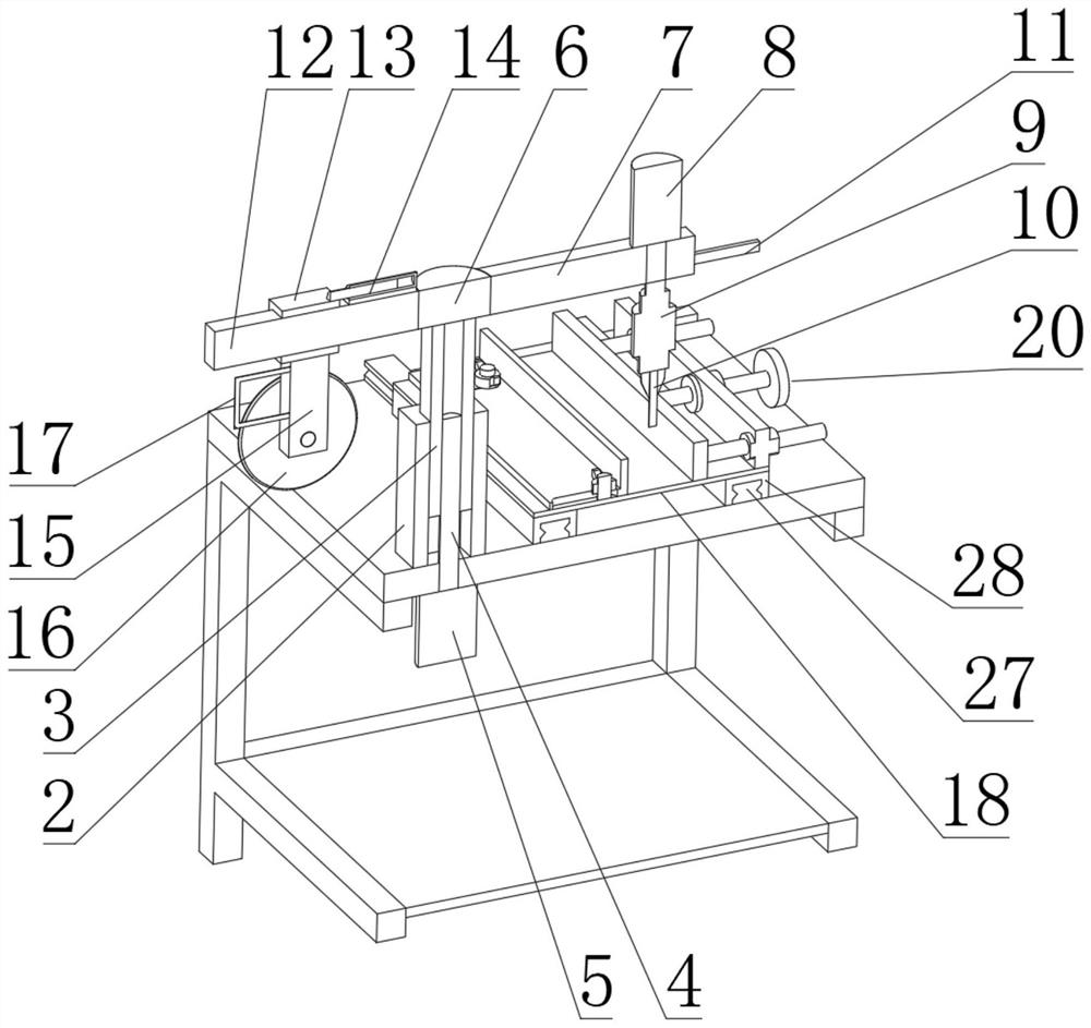
[0023] see Figure 1~4 , in the embodiment of the present invention, the machine tool for producing interlock sewing machine parts includes an operation table 1, a casing 2 is fixedly connected to one side of the top surface of the operation table 1, and the inner wall of the casing 2 is slidably connected with a sliding Rod 3, the inner side of casing 2 is provided with threaded rod 4, and one end of threaded rod 4 is inserted in the slide rod 3, and slide ro...
PUM
 Abstract
Description
Claims
Application Information
PatSnap Eureka turns technology decisions into work you can execute. Powered by our Innovation Knowledge Graph, it runs expert workflows across engineering, life sciences, materials and intellectual property. Get your review-ready output in minutes.


