
Filling equipment for acidification blockage removal liquid processing, acidification blockage removal liquid and oil exploitation method

A filling equipment and workbench technology, which is applied in the field of acidification and blockage removal fluid processing

Pending Publication Date: 2021-05-07
鲁海波
View PDF4 Cites 2 Cited by
  • Summary
  • Abstract
  • Description
  • Claims
  • Application Information

AI Technical Summary

Problems solved by technology

[0003] Aiming at the problem in the prior art that the acidizing and blocking-removing liquid is easily dripped on the outside of the filling cylinder during filling by the filling equipment used for processing the acidizing and blocking-removing liquid, which may cause physical injury to the operator, the present invention provides an acidizing and blocking-removing liquid The filling equipment for liquid blocking processing solves the problems raised in the above-mentioned background technology. It can effectively remove the acidified blocking-removing liquid dripping on the outside of the filling cylinder during the filling process, so that the remaining Acidified plugging solution will not cause harm to operators

Method used


Image

  • Filling equipment for acidification blockage removal liquid processing, acidification blockage removal liquid and oil exploitation method
  • Filling equipment for acidification blockage removal liquid processing, acidification blockage removal liquid and oil exploitation method
  • Filling equipment for acidification blockage removal liquid processing, acidification blockage removal liquid and oil exploitation method

Examples


Embodiment Construction

[0030] The following will clearly and completely describe the technical solutions in the embodiments of the present invention with reference to the accompanying drawings in the embodiments of the present invention. Obviously, the described embodiments are only some, not all, embodiments of the present invention.

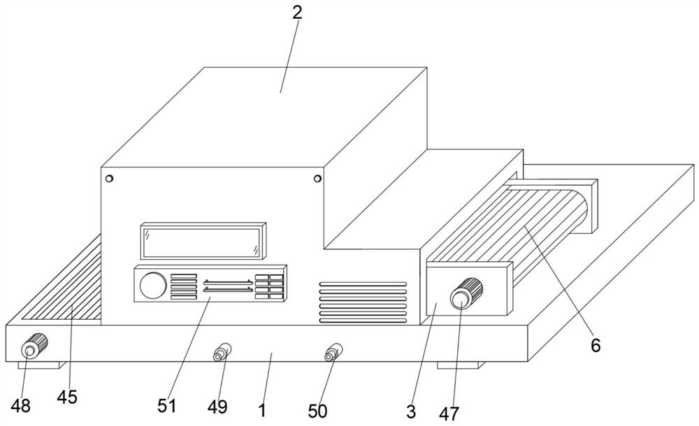
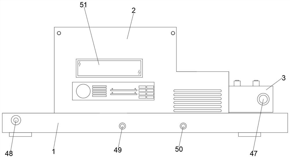
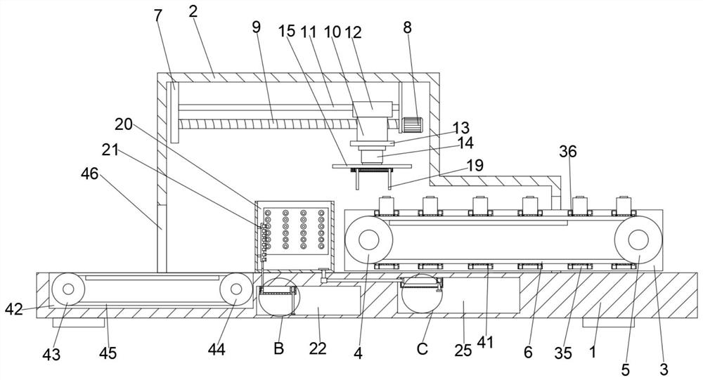
[0031] see Figure 1 to Figure 11, the present invention provides a technical solution: acidification plugging solution processing filling equipment, including a workbench 1, a conveyor belt 45 and a conveyor belt 6, the top of the workbench 1 is fixedly connected to the work box 2, the top of the work box 2 inner cavity Two fixed blocks 7 are fixedly connected, and threaded rods 9 are connected in rotation between the two fixed blocks 7. One side of one of the fixed blocks 7 is fixedly connected with a first servo motor 8, and the output end of the first servo motor 8 is connected to the screw thread. One end of rod 9 is fixedly connected, and the outer thread of th...


PUM


Abstract

The invention discloses filling equipment for acidification blockage removal liquid processing, acidification blockage removal liquid and an oil exploitation method, and relates to the technical field of acidification blockage removal liquid processing. The filling equipment for acidification blockage removal liquid processing comprises a workbench, a transferring belt and a conveying belt, wherein the top of the workbench is fixedly connected with a working box; and the top of an inner cavity of the working box is fixedly connected with two fixing blocks. According to the filling equipment for acidification blockage removal liquid processing, through the arrangement of a water spraying pipe, a water discharging pipe and an air spraying pipe, the water sucking end of a first water pump sucks clean water in a water storage cavity, and then the water spraying pipe sprays the water out to clean the outer side of a filling barrel, so that the acidification blockage removal liquid dripping on the outer side of the filling barrel in the filling process can be effectively removed; and meanwhile, the water sucking end of a second water pump sucks cleaning wastewater in a cleaning box into the water discharging pipe, then the water sucking end of the second water pump sucks the wastewater, and then the water outlet end of the second water pump discharges the wastewater into a wastewater cavity for storage, so that the situation that the wastewater is accumulated in the cleaning box and causes secondary pollution to the filling barrel is prevented.

Description

technical field [0001] The invention relates to the technical field of acidizing and blocking-removing liquid processing, in particular to filling equipment for acidizing and blocking-removing liquid processing, acidizing and blocking-removing liquid, and an oil exploitation method. Background technique [0002] Acidizing plugging removal technology is an effective measure to decontaminate oil and gas reservoirs near wellbore and restore oil and gas well productivity. Acidification: It is to use the chemical dissolution of acid liquid to dissolve formation blockages, expand or extend formation fractures and caves, to restore and improve formation permeability, reduce oil flow resistance or water injection resistance, so as to increase oil well production and water well injection. Purpose. Acidified plug-removing liquid is acidic and corrosive. When the filling machine is filling the filling cylinder, it is easy to drip on the outside of the filling cylinder. The operator's...

Claims


Application Information

Patent Timeline
IPC IPC(8): B65G15/58B65G47/90B08B3/02C09K8/52C09K8/78
CPCB65G15/58B65G47/90B08B3/02C09K8/52C09K8/78
Inventor 同闫锋宋乐
Owner 鲁海波
Learn More