

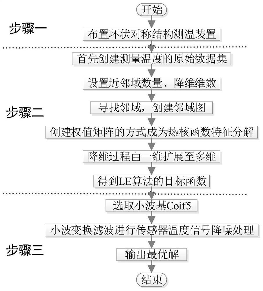
Sensor error identification and elimination method based on Laplacian eigenmapping algorithm
A feature mapping and sensor technology, applied in the field of Laplace feature mapping algorithm, can solve the problems of complex temperature variation law of the plume field of the engine tail flame, poor accuracy of temperature measurement results, weakening and removal of measurement interference, etc. Measurement margin, high accuracy, and the effect of improving accuracy
- Summary
- Abstract
- Description
- Claims
- Application Information
AI Technical Summary
Problems solved by technology
Method used
Image

Examples
specific Embodiment approach
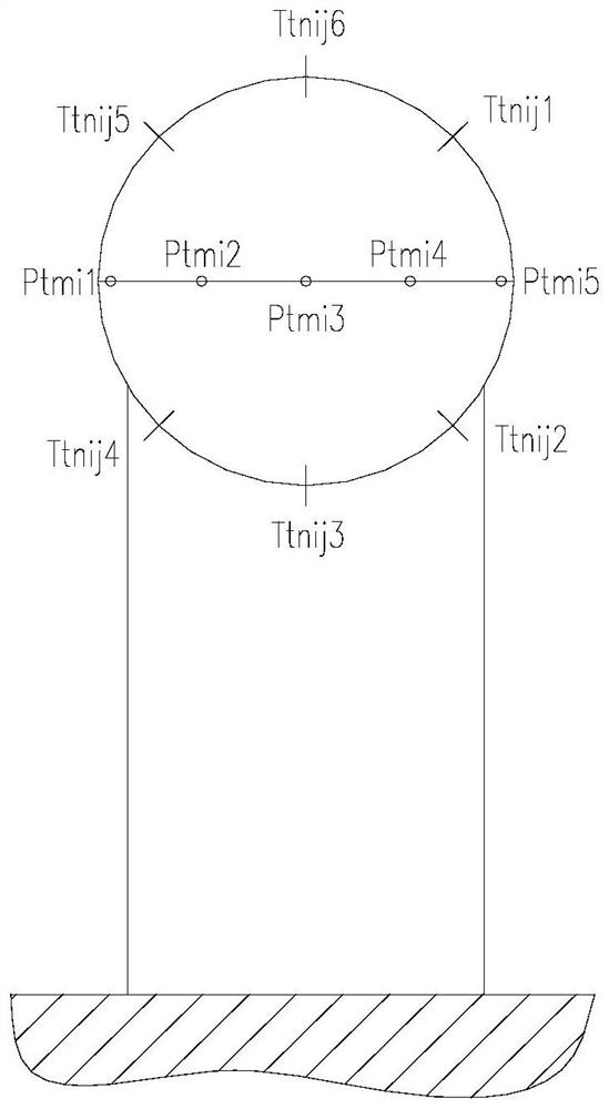
[0043] This test bench uses platinum metal as the temperature sensing element of the sensor, figure 2 It is the axial view of the measuring ring. Its accuracy can reach A-level tolerance (0.15±0.003t°C). The temperature coverage of the platinum resistance sensor is -200°C to 400°C. Design the shell size of the sensor for the point flow rate, put the platinum resistance into the shell, and use the three-wire lead-out line to reduce the error caused by the wire.
[0044] Execution step 1: Take the full temperature and full pressure measuring ring of the engine "0-0" section as an example, figure 2 It is an axial view of the measuring ring, the height of which is coaxial with the engine, installed far in front of the engine intake direction, and used to measure the total intake pressure and total intake temperature of the engine.
[0045] In the embodiment, 6 thermal resistance temperature sensors are used to measure, and the average value is taken 3 times at the end, and a to...
PUM
 Abstract
Description
Claims
Application Information