
End part metal piece structure for transmission insulating rod of gas insulated switchgear and manufacturing method of end part metal piece structure

A technology of gas insulated switches and insulating rods, which is applied to the setting of switchgear, electric switches, switchgear, etc., can solve problems such as poor interface bonding performance, and achieve the goal of improving strength, enhancing bonding strength, and ensuring reliability Effect

Active Publication Date: 2021-05-07
XI AN JIAOTONG UNIV +2
View PDF6 Cites 2 Cited by
  • Summary
  • Abstract
  • Description
  • Claims
  • Application Information

AI Technical Summary

Problems solved by technology

[0005] In order to solve the problems existing in the prior art, the purpose of the present invention is to propose a structure of metal parts at the end of the transmission insulating rod for gas insulated switchgear and its manufacturing method, so as to solve the problem of metal parts and fiber-reinforced epoxy composite pipes. Mechanical and insulation problems caused by poor interface bonding performance

Method used


Image

  • End part metal piece structure for transmission insulating rod of gas insulated switchgear and manufacturing method of end part metal piece structure
  • End part metal piece structure for transmission insulating rod of gas insulated switchgear and manufacturing method of end part metal piece structure
  • End part metal piece structure for transmission insulating rod of gas insulated switchgear and manufacturing method of end part metal piece structure

Examples


Embodiment

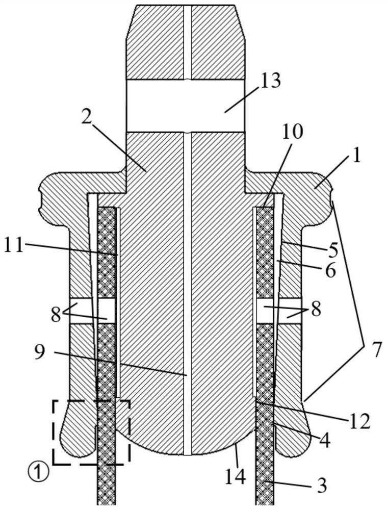
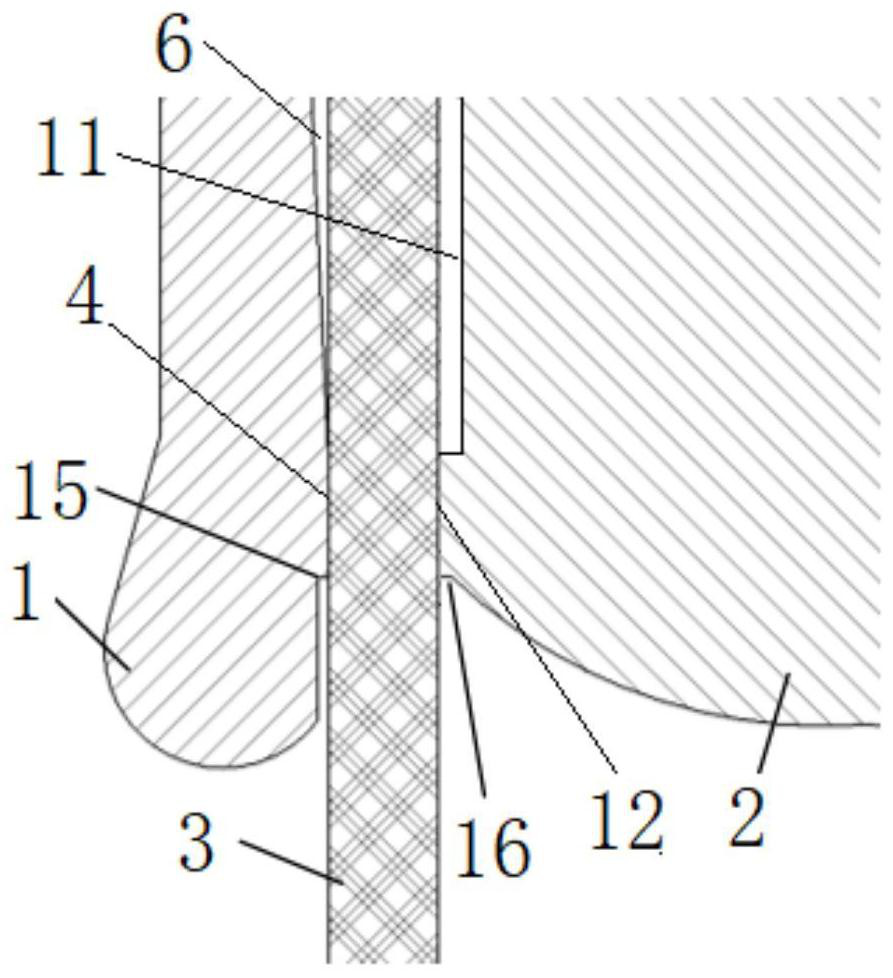
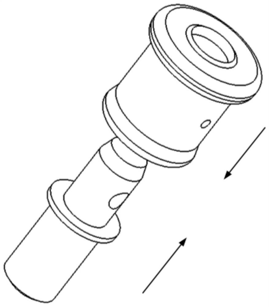
[0043] Such as Figure 1-Figure 3 As shown, in the following description of this embodiment, all use figure 1 and figure 2 The orientation shown is taken as an example for illustration. This embodiment is used for the end metal part structure of the transmission insulating rod of the gas insulated switchgear, including the outer sleeve 1, the metal insert 2, and the fiber-reinforced epoxy as the main insulating body of the pull rod. Composite pipe 3, the inner profile of the outer sleeve 1 includes a second parallel section 4 forming an interference fit with the fiber reinforced epoxy composite pipe 3, an inclined section 5 forming a certain angle with the fiber reinforced epoxy composite pipe 3, and a second Two chamfers 15, a wedge-shaped bonding section 6 (that is, the glue injection cavity) is formed between the inclined section 5 and the fiber-reinforced epoxy composite pipe 3 . The outer contour of the outer sleeve 1 includes an annular groove 7, and the annular groov...


PUM


Abstract

The invention discloses an end metal piece structure for a transmission insulating rod of gas insulated switchgear and a manufacturing method of the end metal piece structure. An outer sleeve of the end metal piece structure sleeves the outside of a metal insert, one end of the metal insert extends out of the outer sleeve, a pin hole is formed in the part, outside the outer sleeve, of the end of the metal insert; a first annular gap is formed between the other end of the metal insert and the other end of the outer sleeve; one end of a fiber reinforced epoxy composite pipe is inserted into an inner cavity of the outer sleeve from the first annular gap; a glue injection cavity is formed between the outer surface of the fiber reinforced epoxy composite pipe and the inner wall of the outer sleeve; the longitudinal section of the glue injection cavity is in a shape with one large end and one small end; and the small end of the glue injection cavity is the end close to the first annular gap, and the glue injection cavity is filled with a binder. According to the end part metal piece structure of the invention, the mechanical and insulation problems caused by poor interface bonding performance between the metal piece and the fiber reinforced epoxy composite pipe are solved.

Description

technical field [0001] The invention belongs to the technical field of structural design optimization of electric power equipment, and in particular relates to the bonding structure of fiber-reinforced epoxy composite pipes and end metal parts of insulating pull rods used in UHV GIS, in particular to an end for transmission insulating rods of gas insulated switchgears. The structure of internal metal parts and its manufacturing method. Background technique [0002] The insulating rod is a key component of UHV gas insulated metal-enclosed switchgear (Gas Insulated Switchgear, GIS). It is the link between the contacts and the operating mechanism of the GIS circuit breaker. The applied impact load is also subjected to the long-term action of the electric field during operation, and its mechanical and electrical performance is related to the safety and stability of the system operation. At present, for GIS circuit breaker insulation pull rods, when the aramid-polyester fiber re...

Claims


Application Information

Patent Timeline
Patent Type & Authority Applications(China)
IPC IPC(8): H01H3/32H01H11/00H02B13/035
CPCH01H3/32H01H11/00H02B13/035
Inventor 彭宗仁吴泽华靳守锋朱思佳吴青松陈允王浩然廖巍胡睿智
Owner XI AN JIAOTONG UNIV
Learn More