Connecting rod type low-resistance feeder
A low-resistance, feeder technology, used in conveyors, vibrating conveyors, solid separation and other directions, can solve the impact of the quality of the aggregate in the desilting process, cannot be screened out of small-sized materials and soil inclusions, and cannot be conveyed obliquely upwards. And other issues
- Summary
- Abstract
- Description
- Claims
- Application Information
AI Technical Summary
Problems solved by technology
Method used
Image
Examples
Embodiment 1
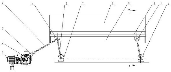
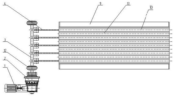
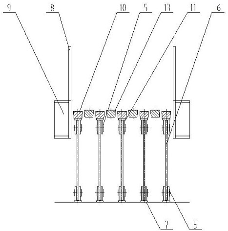
[0024] A connecting rod type low-resistance feeder, comprising a frame 9, a support 7 and a motor 1; side plates 8 are provided on both sides of the frame 9; The first bar 10 and the second bar 13; the support 7 is located below the frame 9; the first bar 10 and the support 7 are hinged for supporting the first bar 10 and driving the first bar 10 A rod 10 moves a swing rod 6; the motor 1 is connected with a crank shaft 3; a connecting rod 4 is hinged between the crank shaft 3 and the swing rod 6; the motor 1 drives the crank shaft 3 to rotate to drive the swing rod 6 movement, so that the first bar 10 and the second bar 13 realize periodic up-and-down circulation dislocation.
[0025] There are two swing rods 6 hinged between the first bar 10 and the support 7, and the joints between the first bar 10, the support 7 and the two swing rods 6 form a parallelogram structure. The main advantage of adopting the parallelogram structure is that the two pendulums are always parallel, ...
Embodiment 2
[0038] The specific difference between embodiment 2 and embodiment 1 is that there is a gap between the first rod 10 and the second rod 13 . By adopting this design, the primary screening of materials can be realized, so that during the transportation of materials, materials smaller than the distance between the first bar 10 and the second bar 13 will fall from the gap, and small pieces of materials and soil can be screened It is beneficial to the crushing and screening treatment of the subsequent process and improves the quality of the final product.
[0039]At the same time, during operation, the first bar 10 periodically pushes the material forward and upward, and periodically moves backward and downward from the material, which reduces the resistance of the system operation and greatly reduces the energy consumption of the equipment operation. Realize the stable feeding of the feeder, and there will be no problems of being crushed or punched by the material. figure 1 It i...
Embodiment 3
[0042] The concrete difference of embodiment 3 and embodiment 2 and embodiment 1 is:
[0043] The first rod 10 in embodiment 3 is a periodic movable structure (refer to embodiment 1 and embodiment 2 for details), and the second rod 13 is also a periodic movable structure (that is, the structural design of the second rod 13 is the same as that of the first rod 13). A stick 10 is consistent, so no more details). It should be noted that: when the first bar 10 and the second bar 13 are in operation, they are misaligned structures and cannot be synchronized. Therefore, after adopting the above-mentioned structural design, the screening efficiency can be further improved, the frequency of dislocation screening between the two can be accelerated, and the material conveying efficiency can be improved.
PUM
 Abstract
Description
Claims
Application Information
 - R&D Engineer
- R&D Manager
- IP Professional
- Industry Leading Data Capabilities
- Powerful AI technology
- Patent DNA Extraction
Browse by: Latest US Patents, China's latest patents, Technical Efficacy Thesaurus, Application Domain, Technology Topic, Popular Technical Reports.
© 2024 PatSnap. All rights reserved.Legal|Privacy policy|Modern Slavery Act Transparency Statement|Sitemap|About US| Contact US: help@patsnap.com


