
Soil curing agent discharging device based on image recognition technology and using method of soil curing agent discharging device

A technology of image recognition and curing agent, which is applied in the direction of emptying containers, loading/unloading, bottle filling, etc. It can solve the problems of waste, heavy workload for workers, inconvenient control of soil curing agent, etc., and achieve simple opening and labor burden for workers Reduced effect

Inactive Publication Date: 2021-05-11
齐谷一
View PDF7 Cites 0 Cited by
  • Summary
  • Abstract
  • Description
  • Claims
  • Application Information

AI Technical Summary

Problems solved by technology

[0003] 1. The traditional dumping method is mostly manual dumping, the workload of the workers is too heavy, and the traditional machine is not convenient for the stable transportation of the barreled soil curing agent;
[0004] 2. The traditional machine is not convenient for positioning and opening the soil curing agent in different barrels;
[0005] 3. The traditional machine will spill part of the soil curing agent when dumping, which is not convenient to reduce the loss of soil curing agent during the dumping process. At the same time, when dumping, it is easy to roll over due to the heavy weight at the beginning, which is not convenient for controlling the soil curing agent. ;
[0006] 4. The traditional machine is not convenient to accurately sense whether there is any remaining soil curing agent in the barrel and it is not poured out, which is easy to cause waste

Method used


Image

  • Soil curing agent discharging device based on image recognition technology and using method of soil curing agent discharging device
  • Soil curing agent discharging device based on image recognition technology and using method of soil curing agent discharging device
  • Soil curing agent discharging device based on image recognition technology and using method of soil curing agent discharging device

Examples


Embodiment Construction

[0032] In the description of the present invention, it should be noted that the orientations or positional relationships indicated by the terms "upper", "lower", "inner", "outer", "top / bottom" etc. are based on the orientations shown in the drawings Or positional relationship is only for the convenience of describing the present invention and simplifying the description, but does not indicate or imply that the device or element referred to must have a specific orientation, be constructed and operated in a specific orientation, and therefore should not be construed as limiting the present invention. In addition, the terms "first" and "second" are used for descriptive purposes only, and should not be understood as indicating or implying relative importance.

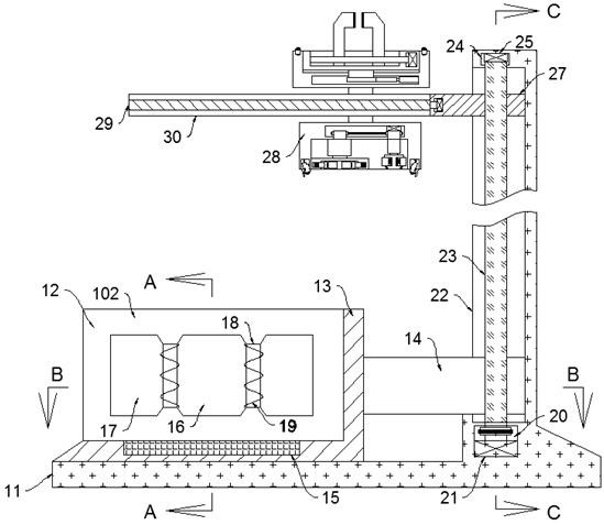
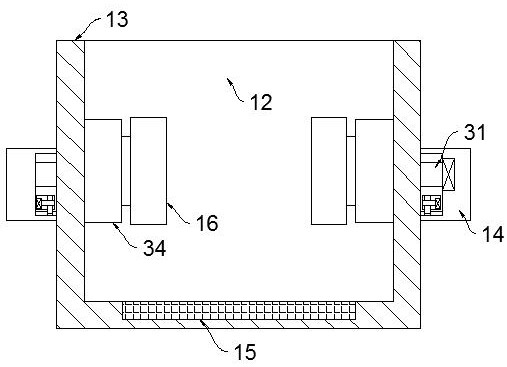
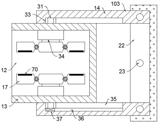
[0033] refer to Figure 1-7 , according to an embodiment of the present invention, a soil curing agent feeder based on image recognition technology includes a frame 11, and the frame 11 is provided with a moving groove 22 w...


PUM


Abstract

The invention discloses a soil curing agent discharging device based on an image recognition technology and an using method of the soil curing agent discharging device. The soil curing agent discharging device comprises a rack, a moving groove with a leftward opening is formed in the rack, threaded columns are rotationally installed on the inner bottom wall of the moving groove in a front-back symmetrical mode, the threaded columns are in threaded connection with travelling grooves slidably formed in the front wall and the rear wall of the moving groove, a first threaded shaft rotationally installed on the top wall of the moving groove is arranged between the threaded columns, the first threaded shaft is in threaded connection with a threaded block slidably connected to the right wall of the moving groove, the threaded block extends leftwards out of the moving groove and is rotationally provided with a placing plate, and electronic sliding rails are symmetrically and fixedly arranged at the upper position and the lower position of the placing plate. According to the soil curing agent discharging device based on the image recognition technology and the using method of the soil curing agent discharging device, whether the residual soil curing agent exists in a barrel or not is judged through a gravity sensor, the barrel rotates and stays for a period of time, and a machine is reset after the weight does not change, so that resources are not excessively wasted.

Description

technical field [0001] The invention relates to the technical field of soil curing agents, in particular to a soil curing agent feeder based on image recognition technology and a method for using the same. Background technique [0002] Soil curing agent is the abbreviation of soil curing admixture. It is a new type of energy-saving and environmental protection engineering material synthesized from a variety of inorganic and organic materials to cure various types of soil. For the soil that needs to be reinforced, according to the physical and chemical properties of the soil, only a certain amount of curing agent needs to be mixed in, mixed and compacted to achieve the required performance indicators. After it is mixed with the soil, it passes through a series of physical and chemical Reacting to change the engineering properties of the soil, it can fix a large amount of free water in the soil in the form of crystal water, reduce the surface current of the soil micelles, thin...

Claims


Application Information

Patent Timeline
Patent Type & Authority Applications(China)
IPC IPC(8): B65G65/23
CPCB65G65/23B65G2201/042
Inventor 齐谷一
Owner 齐谷一
Learn More