
Raw material mixing device for metal powder injection molding and metal powder injection molding method

A technology for metal powder and raw materials, which is applied in the field of raw material mixing devices for metal powder injection molding, can solve the problems of long mixing time, low flow rate of raw materials, and long use time, so as to reduce the time required for discharging and mixing. Efficiency and effect improvement, effect of improving effect and efficiency

Pending Publication Date: 2021-05-14
李梦阳
View PDF4 Cites 2 Cited by
  • Summary
  • Abstract
  • Description
  • Claims
  • Application Information

AI Technical Summary

Problems solved by technology

The existing metal powder injection molding raw material mixing device has a relatively simple structure, a relatively single mixing method, and a low stirring force, resulting in a poor mixing effect of the metal powder raw material and a long time for mixing, which cannot meet the requirements of the metal powder. The actual production needs of powder injection molding; at the same time, the existing metal powder injection molding raw material mixing device is not easy to export the mixed raw materials when discharging. It is not conducive to the rapid use and production of metal powder raw materials

Method used


Image

  • Raw material mixing device for metal powder injection molding and metal powder injection molding method
  • Raw material mixing device for metal powder injection molding and metal powder injection molding method
  • Raw material mixing device for metal powder injection molding and metal powder injection molding method

Examples


Embodiment Construction

[0037] The following will clearly and completely describe the technical solutions in the embodiments of the present invention with reference to the accompanying drawings in the embodiments of the present invention. Obviously, the described embodiments are only some, not all, embodiments of the present invention. Based on the embodiments of the present invention, all other embodiments obtained by persons of ordinary skill in the art without creative efforts fall within the protection scope of the present invention.

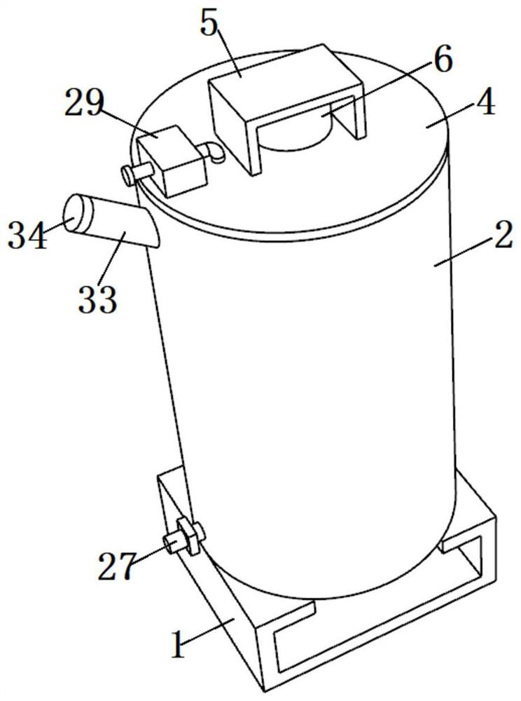
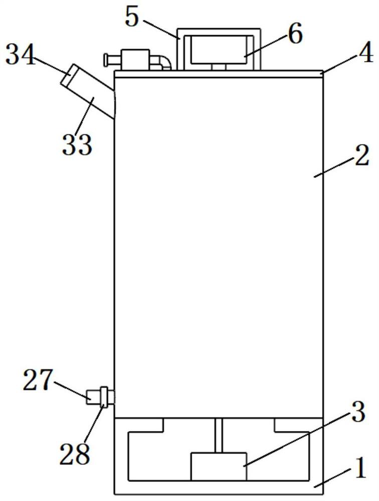
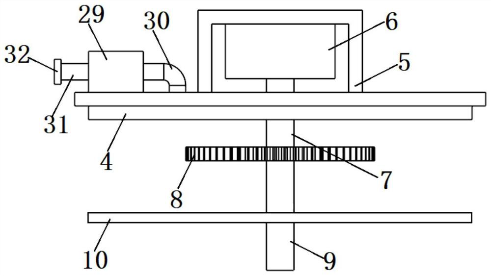
[0038] see Figure 1-7 , the present invention is a raw material mixing device for metal powder injection molding, comprising a support base 1 and a gathering hopper 11, a mixing cylinder 2 is fixed on the top of the support base 1, a first motor 3 is fixed on the inner wall of the support base 1, The top of the mixing cylinder 2 is fixed with a cover plate 4, the top of the cover plate 4 is fixed with a supporting plate 5, the inner wall of the supporting plate 5 ...


PUM


Abstract

The invention discloses a raw material mixing device for metal powder injection molding and a metal powder injection molding method, and relates to the technical field of metal powder application. The raw material mixing device comprises a support seat and a gathering hopper; the top of the support seat is fixedly provided with a mixing cylinder, a first motor is fixed to the inner wall of the first supporting seat; a cover plate is fixed to the top of the mixing cylinder; a supporting plate is fixed to the top of the cover plate; a second motor is fixed to the inner wall of the first supporting plate; and one end of an output shaft of the second motor is fixedly provided with a first support rod. The second motor synchronously drives a plurality of first spiral augers to rotate in a gear transmission manner, so that the first spiral augers are matched with material conveying pipes to drive raw materials in the mixing cylinder to be stirred up and down; the plurality of material conveying pipes are distributed in a circular array and the length of the material conveying pipes is gradually reduced along the clockwise direction, so the raw materials at different depth positions in the mixing cylinder can collide in the material gathering hopper and are further fully mixed under the action of a plurality of second stirring rods, so that the effect and the efficiency of uniformly mixing the raw materials can be remarkably improved.

Description

technical field [0001] The invention belongs to the technical field of metal powder application, in particular to a raw material mixing device for metal powder injection molding and a metal powder injection molding method. Background technique [0002] Metal powder refers to a group of metal particles whose size is less than 1 mm. Including single metal powder, alloy powder and some refractory compound powder with metal properties, it is the main raw material of powder metallurgy. The metal substance is generally silvery white. When the metal is under certain conditions, it is black powder. Most metal powders are black. The preparation and application of metal powder have a long history. In ancient times, gold, silver, copper, bronze and some oxide powders were used as coatings for the coloring and decoration of pottery, jewelry and other utensils. Metal powder is a loose substance, and its performance comprehensively reflects the properties of the metal itself, the prope...

Claims


Application Information

Patent Timeline
IPC IPC(8): B01F7/18B01F7/24B01F15/02B22F1/00B22F3/22
CPCB22F1/0003B22F3/225B01F27/1921B01F27/92B01F27/90B01F35/714B01F35/71B01F35/75
Inventor 李梦阳
Owner 李梦阳
Learn More