
Robot welding device for movable arm plate of loading machine

A robot welding and arm plate technology, applied in auxiliary devices, welding equipment, welding equipment, etc., can solve the problems of weak flange welding, shaking of rotating frame, flange deviation, etc.

Active Publication Date: 2021-05-14
山东明宇重工机械有限公司
View PDF8 Cites 5 Cited by
  • Summary
  • Abstract
  • Description
  • Claims
  • Application Information

AI Technical Summary

Problems solved by technology

[0005] (1) The two sides of the rotating frame of the device are the loading and unloading area and the welding area respectively. After the rotating frame is turned over, the side of the fixed plate of the rotating frame close to the loading and unloading area is fixed on the side of the loader arm plate, and then rotated to the welding area Finally, the side of the fixed plate that fixes the arm plate of the loader faces downward, and the rotating frame cannot realize that the side of the fixed plate that fixes the arm plate of the loader faces upward in the loading and unloading area and the welding area, which hinders the loading of the robot in the welding area. Flange welding steps for the mobile arm plate
[0006] (2) The robot of this device grabs the flange and transports it to the arm plate of the loader. The weight of the fixed plate changes, and the center of gravity tends to move downward. Before welding, the robot’s air gripper must loosen the flange. In order to drive the automatic welding gun to weld the welding position of the flange plate and the arm plate of the loader, it cannot be realized at the same time, so that the flange plate cannot be positioned during welding, resulting in deviations in the position of the flange plate
[0007] (3) After the rotating frame rotates, the fixed position after the fixed plate rotates to a fixed angle has no auxiliary positioning components, so that after the fixed plate rotates to the welding area, the rotating frame will shake during the welding process, resulting in deviation of the welding position. The welding of the blue plate is not firm, causing the rotation interference of the arm plate of the loader

Method used


Image

  • Robot welding device for movable arm plate of loading machine
  • Robot welding device for movable arm plate of loading machine
  • Robot welding device for movable arm plate of loading machine

Examples


Embodiment Construction

[0038] The present invention will be described in detail below, and the technical solutions in the embodiments of the present invention will be clearly and completely described. Apparently, the described embodiments are only some of the embodiments of the present invention, not all of them. Based on the embodiments of the present invention, all other embodiments obtained by persons of ordinary skill in the art without making creative efforts belong to the protection scope of the present invention.

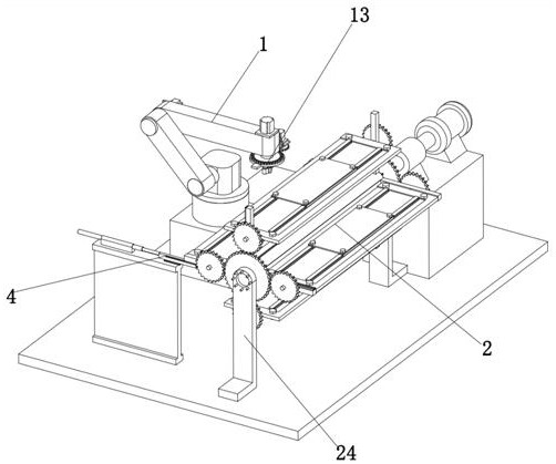
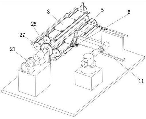
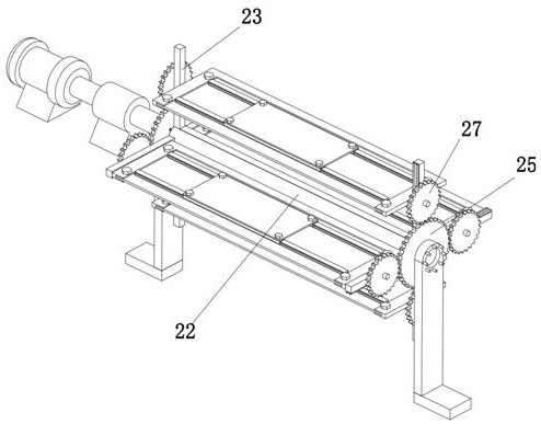
[0039] The present invention provides herein a robotic welding device for loader arm plates through improvements such as Figure 1-Figure 11As shown, the robot welding device includes a robot welding mechanism 1 and a rotating frame 2, and the rotating frame 2 includes a rotating motor 21, a horizontally arranged rotating shaft 22, several working pallets 3 with a rectangular structure and two respectively The cross fixing frame 23 fixedly installed at both ends of the rotating sha...


PUM


Abstract

The invention relates to the technical field of robot welding, specifically to a robot welding device for a movable arm plate of a loading machine. The robot welding device comprises a robot welding mechanism and a rotating frame; the rotating frame comprises a rotating motor, a horizontally arranged rotating shaft, a plurality of work supporting plates and two cross fixed frames; rotating column heads are fixedly mounted at the midpoints of the two ends of each work supporting plate; bearing seats are rotatably mounted at the two ends of the rotating shaft; fixed gears are arranged on the opposite sides of the two bearing seats; rotating gears are fixedly mounted on the rotating column heads; the robot welding mechanism comprises a limiting mechanism and a plurality of robots; and a clamping and welding mechanism is mounted at the output end of each robot. In the processes of feeding, discharging and welding, the movable arm plate is always located over a mounting table, so that the problem that the fixed movable arm plate faces downwards when being overturned to the other side of the rotating frame is solved; and welding is performed in the clamping process, so that the flange plate positioning accuracy is improved.

Description

technical field [0001] The invention relates to the technical field of robot welding, in particular to a robot welding device for a loader arm plate. Background technique [0002] The arm plate of the loader is now manually assembled and welded, and the flange is manually assembled, manually spot-welded, and manually welded. The assembly accuracy is poor, the coaxiality between the inner hole of the flange and the inner hole of the boom plate is poor, the quality of the manual welding seam is unstable, the welding time is long, and the production efficiency is low. [0003] A patent No. CN201911331427.9 is disclosed. The workpiece displacement group of a robot welding device for the arm plate of the loader includes a mounting frame, a servo motor, a rotating frame, a workpiece, a buckle and a fixing plate. The servo motor Fixedly installed on one side of the mounting frame, the rotating shaft of the servo motor is fixedly connected to the rotating frame, a fixing plate for ...

Claims


Application Information

Patent Timeline
IPC IPC(8): B23K31/02B23K37/02B23K37/04
CPCB23K31/02B23K37/0252B23K37/0435
Inventor 衣学航宋希龙刘元铭孙浩王国皓
Owner 山东明宇重工机械有限公司
Learn More